Lumbar disc herniation rehabilitation diagnosis and treatment bed

A lumbar disc herniation, diagnosis and treatment bed technology, applied in physical therapy, medical science, fractures, etc., to achieve the effect of promoting health recovery, reducing vibration frequency, and increasing vibration intensity

Active Publication Date: 2018-06-22
勾志静
View PDF6 Cites 11 Cited by
  • Summary
  • Abstract
  • Description
  • Claims
  • Application Information

AI Technical Summary

Problems solved by technology

[0004] Aiming at the problem that the current existing traction bed for lumbar disc herniation still has defects, the present invention provides a lumbar disc herniation rehabilitation diagnosis and t

Method used


Image

  • Lumbar disc herniation rehabilitation diagnosis and treatment bed
  • Lumbar disc herniation rehabilitation diagnosis and treatment bed
  • Lumbar disc herniation rehabilitation diagnosis and treatment bed

Examples


Embodiment 1

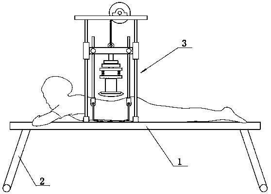
[0022] Embodiment 1: as figure 1 In the shown lumbar disc herniation rehabilitation diagnosis and treatment bed, the bed body includes at least a bed board 1 and support legs 2, and the support legs 2 are fixed or foldable. A vertical traction vibration device 3 is arranged on the bed body. Depend on figure 1 It can be seen that in this embodiment, the patient with lumbar disc herniation is placed in a prone position, and then the vertical traction vibration device 3 is used to lift the human body's waist upwards, so that the posterior arch of the lumbar spine becomes smaller and the posterior lateral position of each vertebral body is enlarged. Then, by controlling the height and vibration intensity of the vibrating motor 308, the posterior arch area of ​​the lumbar spine is vibrated to achieve the purpose of promoting the vertebral nucleus to flow into the annulus fibrosus.

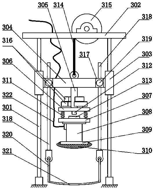
[0023] Such as figure 2 As shown, the vertical traction and vibrating device 3 includes four sym...

Embodiment 2

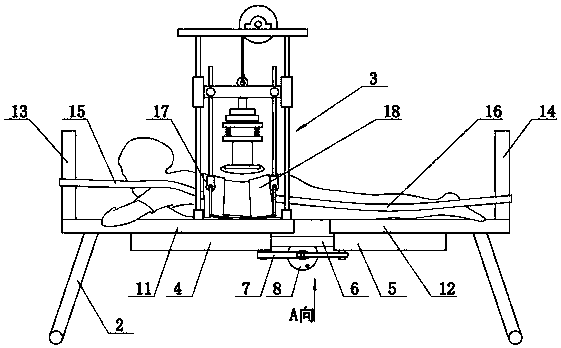
[0029] Embodiment 2: On the basis of embodiment 1, the bed body is designed as a transverse traction bed, see image 3 As shown, the transverse traction bed includes a front board and a rear board, and both the front board and the rear board are provided with support legs 2 . Moreover, the front fixed sleeve 4 and the rear fixed sleeve 5 are respectively fixed at the bottom center of the front bed board and the rear bed board, and the inner sleeve 6 is sleeved on the inside of the front fixed sleeve 4 and the rear fixed sleeve 5 .

[0030] A transverse jack 7 is connected between the front fixed sleeve 4 and the rear fixed sleeve 5 . Such as Figure 4 As shown, the horizontal jack 7 includes four connecting rods hinged from head to tail in turn to form a rhombus-shaped telescopic frame. The shafts are respectively fixed under the front fixed sleeve 4 and the rear fixed sleeve 5, side pin shafts are hinged between the adjacent front connecting rods and rear connecting rods, a...

Embodiment 3

[0039] Embodiment 3: On the basis of Embodiment 1 or 2, a weight 316 is movably fitted outside the middle connecting rod 305 . Vibration intensity can be changed by adding or subtracting weights 316 outside the middle link 305 .


PUM


Abstract

The invention discloses a lumbar disc herniation rehabilitation diagnosis and treatment bed, comprising a bed body; a vertical traction vibrating device is arranged on the bed body; the top of each fixed pillar of the vertical traction vibrating device is sleeved with a sliding sleeve, cross sliding beams are fixed among the sliding sleeves, a middle connection rod is downwardly fixed to the middle of each cross sliding beam, a tray is vertically fixed to the lower ends of the middle connection rods, a motor seat parallel to the tray is arranged below the tray, and push-pull springs are connected between the periphery of the tray and the periphery of the motor seat. A patient with lumbar disc herniation lies prostrate, the vertical traction vibrating device is used to lift the waist so that the lumbar posterior arch degree is decreased and posterior gaps of vertebras are enlarged, the height and vibration strength of the vibrating motor are then controlled to vibrate the lumbar posterior arch area, and therefore, healthy recovery of lumbar disc herniation can be substantially promoted in mechanical manner.

Description

Technical field: [0001] The invention belongs to the technical improvement of lumbar disease treatment instruments in the medical field, and in particular relates to a rehabilitation diagnosis and treatment bed for lumbar disc herniation. Background technique: [0002] The increase of modern people's work pressure, commuting by car, sitting in the office, in front of the computer or playing mahjong for a long time, and the unhealthy living habits of young people, coupled with the reduction in exercise, have gradually contributed to the incidence of lumbar spondylosis, low back pain, sciatica, and cervical spondylosis. rise. At present, in the non-surgical treatment of cervical and lumbar diseases, traction treatment is one of the most commonly used methods. Traction mainly uses mechanical force to tract the intervertebral space and intervertebral facet joints, thereby changing the internal pressure and gap of the intervertebral disc, making the protrusion The compression on...

Claims


Application Information

Patent Timeline
IPC IPC(8): A61F5/042A61H1/02A61H23/02
CPCA61F5/0104A61F5/042A61H1/0218A61H1/0292A61H23/02A61H2201/0142A61H2201/1207A61H2205/08Y02A50/30
Inventor 勾志静陈靖军冀玉霞
Owner 勾志静
Why Eureka
Try Eureka