Optimization designing method of flue structure for reducing pressure loss of SCR denitrification device

An optimized design and denitrification technology, which is applied in chemical instruments and methods, separation methods, gas treatment, etc., can solve problems not involved in the optimal design of flue shape, and achieve the effect of reducing the application potential of self-use electricity consumption and reducing pressure loss

Inactive Publication Date: 2018-06-22
上海电气电站环保工程有限公司 +1
View PDF2 Cites 2 Cited by
  • Summary
  • Abstract
  • Description
  • Claims
  • Application Information

AI Technical Summary

Problems solved by technology

[0004] After searching the existing technical literature, it was found that Wang Zhiqiang, Zou Jinsheng, Xiao Hongchuan, Chen Peng, and Chang Jingcai published a paper on "SCR Reactors in the Journal of Environmental Engineering" (Volume 5, Issue 3, Page 631, 2011). Research on the Effect of Key Components on System Pressure Loss Characteristics", this paper analyzes the influence of key components in the SCR reactor (deflector, wear plate of ammonia injection device, rectifier), and the design method proposed can reduce the internal pressure of the denitrification device. loss, but does not involve the optimal design of flue shape to reduce pressure loss

Method used


Image

  • Optimization designing method of flue structure for reducing pressure loss of SCR denitrification device
  • Optimization designing method of flue structure for reducing pressure loss of SCR denitrification device
  • Optimization designing method of flue structure for reducing pressure loss of SCR denitrification device

Examples


Embodiment Construction

[0028] The present invention will be described in detail below in conjunction with specific embodiments. The following examples will help those skilled in the art to further understand the present invention, but do not limit the present invention in any form. It should be noted that those skilled in the art can make several modifications and improvements without departing from the concept of the present invention. These all belong to the protection scope of the present invention.

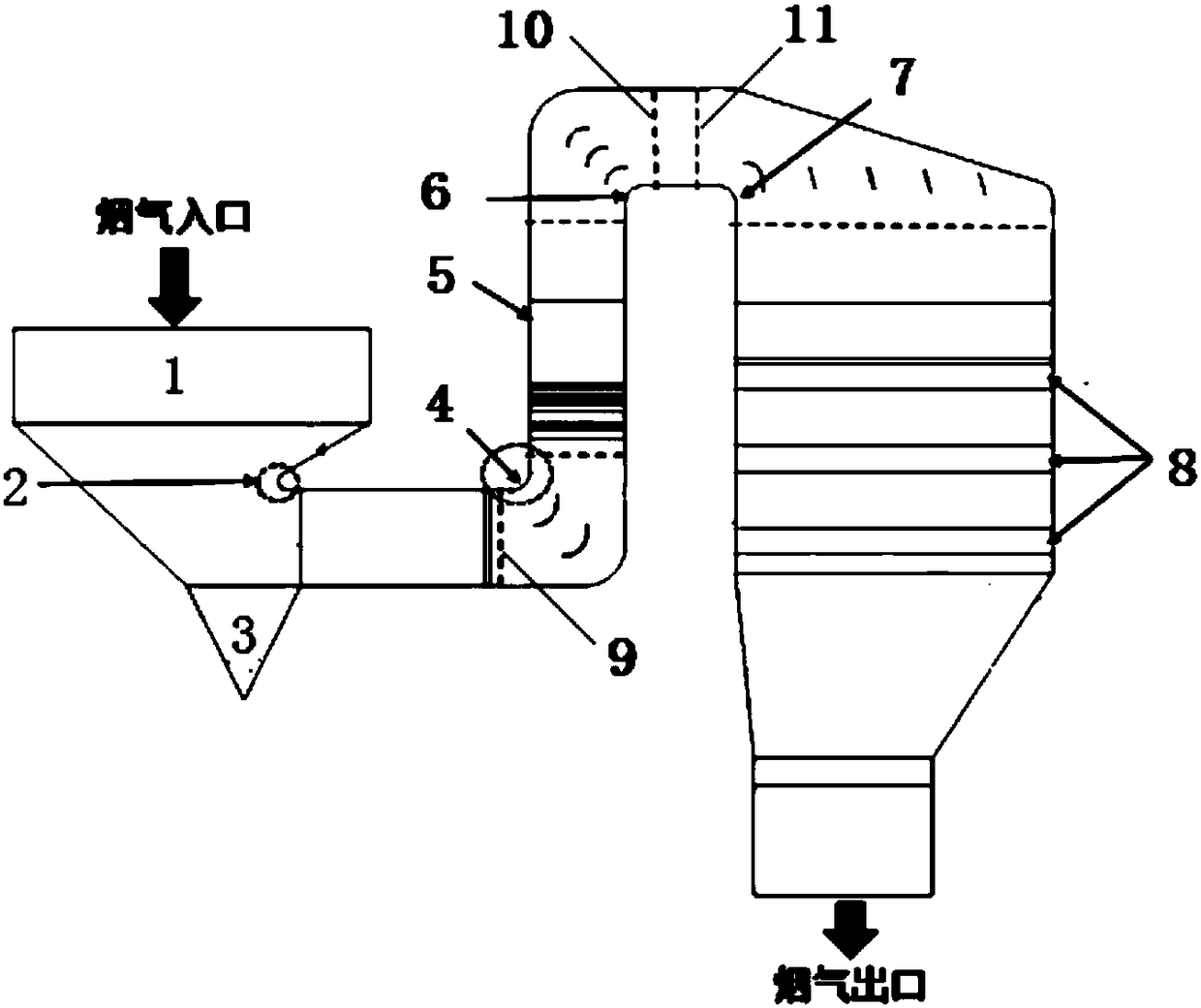
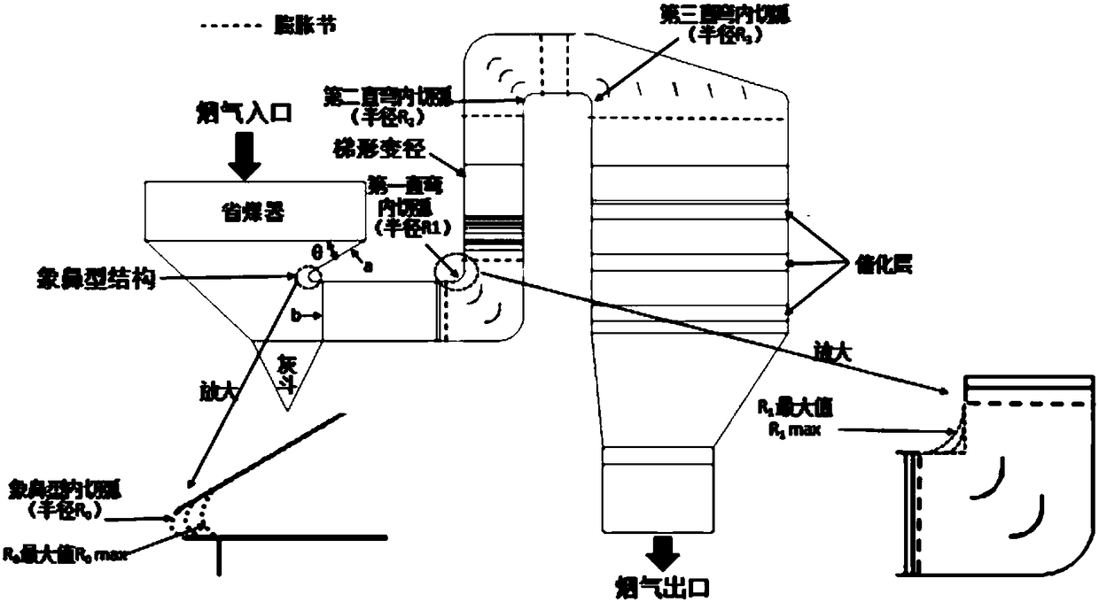
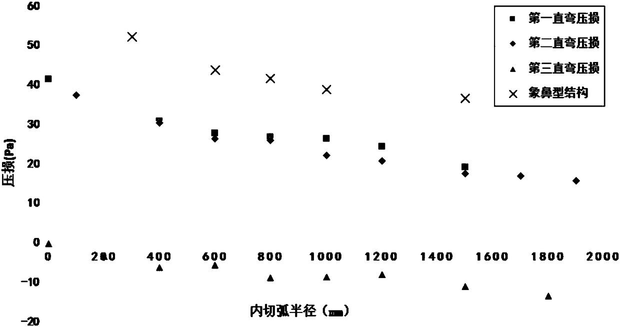
[0029] The invention provides a flue shape optimization design method for reducing the pressure loss of the SCR denitrification device on the premise of meeting the uniformity requirements of the flue gas velocity field above the catalytic layer. 1. Optimal design of the radius of the inscribed arc of the second and third straight bends to reduce system pressure loss. Among them: the radius R of the inscribed arc of the elephant trunk structure of the economizer 0 , the radius R of the inscribed ...


PUM


Abstract

The invention provides an optimization designing method of a flue structure for reducing pressure loss of an SCR denitrification device. According to the method, optimization designing is conducted onthe radius of internally tangent arcs of various bends under the premise that the plane flue gas velocity distribution relative standard deviation above a catalyst layer is sufficiently low, so thatthe pressure loss of each bend is minimized within a given radius range; optimized flue shape parameters comprise the inner tangent arc radius of an elephant-trunk-like structure of an economizer, andthe inner tangent arc radius of first, second, third right-angled bends of a pi-type denitrification device. The pressure loss of the denitrification device is an important indicator affecting the energy consumption of a thermal power induced draft fan, and for a 1000MW unit, every reduced 10Pa of the pressure loss leads to 140,000 kilowatt-hour reduction of the self-use electricity consumption of the induced draft fan every year, so that low-pressure-loss shape designing of the denitrification device has a realistic meaning of energy saving and efficiency enhancing on a power plant; in addition, the optimization designing of the flue gas structure does not generate negative impacts on the flue gas velocity field uniformity above the catalyst layer but increases the uniformity of the fluegas velocity field, which means the velocity distribution standard deviation of the flue gas velocity field is reduced.

Description

technical field [0001] The invention belongs to the technical field of thermal power optimization operation, and in particular relates to a flue shape optimization design method for reducing the pressure loss of an SCR denitrification device on the premise of meeting the uniformity requirement of the flue gas velocity field above the catalytic layer. Background technique [0002] Selective catalytic reduction (SCR-Selective Catalytic Reduction) technology is currently the most widely used flue gas purification technology for coal-fired units. The principle is that the reducing agent (usually ammonia) and nitrogen oxides (NO x ) at V 2 o 5 / WO 3 / TiO 2 or V 2 o 5 / MoO 3 / TiO 2 The oxidation-reduction reaction carried out under the action of the catalyst composed of nitrogen gas (N 2 ) and water (H 2 O), so as to remove the harmful NO in the flue gas x (in NO and NO 2 mainly). When designing a denitrification device, the relative standard deviation of the flue gas...

Claims


Application Information

Patent Timeline
Patent Type & Authority Applications(China)
IPC IPC(8): B01D53/90B01D53/56
CPCB01D53/8631B01D53/90B01D2251/2062B01D2258/0283
Inventor 邓云天袁景淇郭士义李少远赵丹王景成陆良樑陆晶顾潇力王真曾豪骏
Owner 上海电气电站环保工程有限公司
Why Eureka
Try Eureka