Soil remediation treatment device

A technology of soil remediation and excavation, which is applied in the field of soil governance, can solve the problems of uneven soil governance and poor governance effect, and achieve the effects of increasing governance effect, constant soil volume, and improving governance effect

Active Publication Date: 2018-06-22
刘艳燕
8 Cites 36 Cited by

AI-Extracted Technical Summary

Problems solved by technology

[0003] Most of the soil treatment is to spray liquid chemical reagents onto the sudden surface to achieve th...

Method used

Described mixing barrel 15 rotation is arranged in mixing chamber 2, and the left end rotating shaft of mixing barrel 15 runs through mixing chamber 2 and is connected with first rotating shaft 8 rotation by belt, and the left end rotating shaft of mixing barrel 15 is connected in mixing chamber 2 On the side wall of the mixing barrel 15, the left end rotating shaft of the mixing barrel 15 is a hollow structure, and its inner side is rotationally connected with a second rotating shaft 16, and the left end of the second rotating shaft 16 extends into the mixing barrel 15 and is rotationally connected with the right end of the mixing barrel 15 , the left end of the second rotating shaft 16 protrudes from the mixing chamber 2 and is fixedly connected with the bevel gear D21, the bevel gear D21 meshes with the bevel gear C20 fixedly installed at the lower end of the crankshaft 11, and when the crankshaft 11 rotates, the bevel gear C20 and the bevel gear D21 The meshing effect drives the second rotating shaft 16 to rotate, and the stirring rod 17 is symmetrically installed on the second rotating shaft 16. When the stirring rod 17 rotates, the soil and the treatment agent in the mixing bucket 15 are stirred, so that the soil and the agent are fully mixed. contact, and then improve the treatment effect of the soil; the second rotating shaft 16 and the stirring rod 17 are hollow structures, and the left end of the second rotating shaft 16 communicates with the conduit 23 through the rotary joint, and the conduit 23 communicates with the water pump 22, and the stirring rod 17 is provided with a liquid outlet, and the water pump 22 transports the medicine in the treatment agent box 3 to the second rotating shaft 16, and then transports it to the mixing bucket 15...

Abstract

The invention discloses a soil remediation treatment device. The soil remediation treatment device comprises a crushing cavity, a mixing cavity, a treatment agent box and a mixing barrel; the crushingcavity is arranged at the upper end of the mixing cavity and communicates with the mixing cavity through a first soil outlet; the mixing barrel is connected in the mixing cavity in a rotating mode; an annular baffle sleeves the outer side of the mixing barrel; a soil inlet is formed in the side edge of the annular baffle and communicates with the mixing barrel; a second soil outlet is formed in the lower end of the mixing cavity; a feeding hopper is arranged at the upper end of the crushing cavity; a motor is arranged on the right side of the feeding hopper; an output shaft of the motor is connected to a first rotating shaft in a rotating mode through a belt; and the mixing barrel is arranged in the mixing cavity in a rotating mode. The soil remediation treatment device has the advantagesof being novel in design and easy to operate, soil is stirred when the soil is crushed and an agent is added, so that the agent can make full contacted with the soil, the soil can be treated thoroughly, and therefore the defect that the soil is not comprehensively treated can be overcome, and the treatment effect can be improved.

Application Domain

Technology Topic

Treatment effectSoil governance +2

Image

  • Soil remediation treatment device
  • Soil remediation treatment device

Examples

  • Experimental program(1)

Example Embodiment

[0020] The following will clearly and completely describe the technical solutions in the embodiments of the present invention with reference to the accompanying drawings in the embodiments of the present invention. Obviously, the described embodiments are only some, not all, embodiments of the present invention. Based on the embodiments of the present invention, all other embodiments obtained by persons of ordinary skill in the art without making creative efforts belong to the protection scope of the present invention.
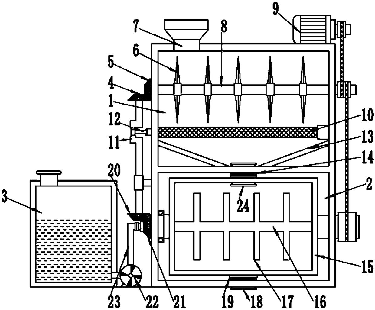
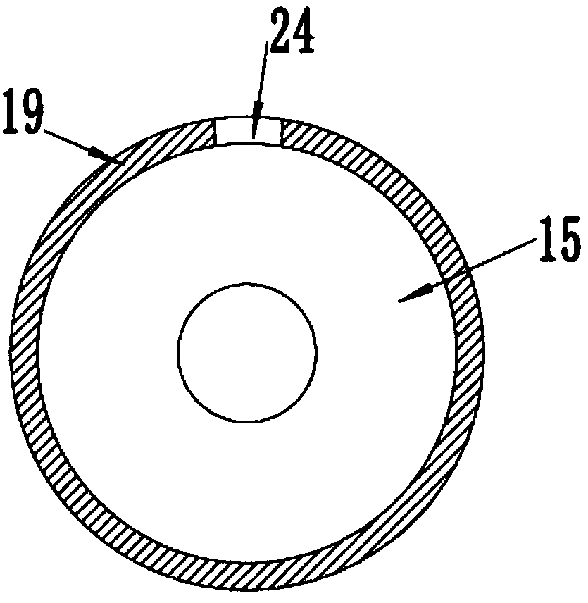
[0021] see Figure 1~2 , a soil remediation treatment device, including a crushing chamber 1, a mixing chamber 2, a treatment agent box 3 and a mixing bucket 15; A mixing bucket 15 is rotatably connected, and the outer side of the mixing bucket 15 is provided with an annular baffle 19, and the side of the annular baffle 19 is provided with a soil inlet 24, and the soil inlet 24 communicates with the mixing bucket 15, and the mixing chamber 2. The lower end is also provided with a second excavation port 18. When the mixing bucket 15 rotates, when the soil inlet 24 is connected with the first soil inlet 14, the soil in the crushing chamber 1 enters the mixing bucket 15. When the soil inlet 24 is connected to the first soil inlet When the two outlets 18 are connected, the soil mixed with the medicament in the mixing barrel 15 falls out from the second outlet 18, thereby realizing the effect of intermittent feeding and intermittent feeding; the left end of the mixing chamber 2 is provided with a treatment agent box 3. A water pump 22 is provided at the right end of the treatment agent box 3 , and the water pump 22 communicates with the treatment agent box 3 through a conduit 23 .
[0022] The upper end of the crushing chamber 1 is provided with a feed hopper 7, and the right side of the feed hopper 7 is provided with a motor 9, and the output shaft of the motor 9 is rotationally connected with the first rotating shaft 8 through a belt, and the first rotating shaft 8 runs through the crushing chamber 1 And it is fixedly connected with the bevel gear B5, the bevel gear B5 meshes with the bevel gear A4 fixedly installed on the upper end of the crankshaft 11, the crankshaft 11 is connected with the connecting rod 12 in rotation, the other end of the connecting rod 12 is hinged with the sieve plate 10, the sieve plate 10 runs through the crushing chamber 1 and is slidably connected with the crushing chamber 1. When the crankshaft 11 rotates, the connecting rod 12 drives the sieve plate 10 to move left and right, thereby screening out the soil that meets the crushing requirements and improving the screening effect. The soil is driven left and right to improve the crushing efficiency; multiple groups of cutting knives 6 are symmetrically installed on the first rotating shaft 8, and the cutting knives 6 crush the soil to facilitate subsequent processing; the inner lower end of the crushing chamber 1 is provided with a bottom plate 13, The bottom plate 13 is in the shape of a rounded table, and the effect of the bottom plate 13 is to concentrate the soil that has been crushed to meet the requirements on the first excavation port 14 and fall out.
[0023] The mixing barrel 15 is rotatably arranged in the mixing chamber 2, and the left end rotating shaft of the mixing barrel 15 runs through the mixing chamber 2 and is rotatably connected with the first rotating shaft 8 through a belt. Above, the shaft at the left end of the mixing bucket 15 is a hollow structure, and the inner side is rotatably connected with a second rotating shaft 16, and the left end of the second rotating shaft 16 extends into the mixing bucket 15 and is rotatably connected with the inner right end of the mixing bucket 15. The left end of the rotating shaft 16 extends out of the mixing chamber 2 and is fixedly connected with the bevel gear D21. The bevel gear D21 meshes with the bevel gear C20 fixedly installed at the lower end of the crankshaft 11. When the crankshaft 11 rotates, it is driven by the meshing action of the bevel gear C20 and the bevel gear D21. The second rotating shaft 16 rotates, and the stirring rod 17 is symmetrically installed on the second rotating shaft 16. When the stirring rod 17 rotates, the soil in the mixing bucket 15 and the treatment agent are stirred, so that the soil and the agent are fully mixed and contacted, and then Improve the treatment effect of the soil; the second rotating shaft 16 and the stirring rod 17 are hollow structures, the left end of the second rotating shaft 16 communicates with the conduit 23 through the rotary joint, the conduit 23 communicates with the water pump 22, and the stirring rod 17 is provided with There is a liquid outlet, and the pump 22 transports the medicine in the treatment agent box 3 to the second rotating shaft 16, and then transports it to the mixing bucket 15 through the liquid outlet on the stirring rod 17, and the stirring rod 17 stirs the soil. During the process, the agent is not sprayed from the stirring rod 17, which can effectively improve the mixing efficiency of the soil and the agent, thereby increasing the effect of soil treatment.
[0024] It will be apparent to those skilled in the art that the invention is not limited to the details of the above-described exemplary embodiments, but that the invention can be embodied in other specific forms without departing from the spirit or essential characteristics of the invention. Accordingly, the embodiments should be regarded in all points of view as exemplary and not restrictive, the scope of the invention being defined by the appended claims rather than the foregoing description, and it is therefore intended that the scope of the invention be defined by the appended claims rather than by the foregoing description. All changes within the meaning and range of equivalents of the elements are embraced in the present invention. Any reference sign in a claim should not be construed as limiting the claim concerned.
[0025] In addition, it should be understood that although this specification is described according to implementation modes, not each implementation mode only contains an independent technical solution, and this description in the specification is only for clarity, and those skilled in the art should take the specification as a whole , the technical solutions in the various embodiments can also be properly combined to form other implementations that can be understood by those skilled in the art.

PUM

no PUM

Description & Claims & Application Information

We can also present the details of the Description, Claims and Application information to help users get a comprehensive understanding of the technical details of the patent, such as background art, summary of invention, brief description of drawings, description of embodiments, and other original content. On the other hand, users can also determine the specific scope of protection of the technology through the list of claims; as well as understand the changes in the life cycle of the technology with the presentation of the patent timeline. Login to view more.

Similar technology patents

Classification and recommendation of technical efficacy words

Why Eureka
Try Eureka