Die locking mechanism for die casting machine directly driven by frameless combined type permanent magnet synchronous linear motor

A permanent magnet synchronous linear and combined technology, applied to synchronous motors with stationary armatures and rotating magnets, synchronous machine parts, magnetic circuit shape/style/structure, etc., can solve the difficulty of design, manufacture and assembly Increased size, greater loss of transmission efficiency and precision, and increased number of transmission components, etc., to achieve the effects of improving drive efficiency, fast response speed, and reducing volume

Pending Publication Date: 2018-06-22
HUBEI HUANYEE ELECTROMAGNETIC EQUIP ENG TECH CO LTD
View PDF0 Cites 7 Cited by
  • Summary
  • Abstract
  • Description
  • Claims
  • Application Information

AI Technical Summary

Problems solved by technology

[0003] At present, there are more and more types of die-casting machines, more and more perfect functions, and more and more complex structures. As the core mechanism of die-casting machines, the mold clamping mechanism is generally composed of hydraulic pressure, gears, connecting rods and other transmission devices. There are many links, and the efficiency and accuracy of the transmission are greatly lost. At the same time, due to the increase in the number of transmission components, the performance is affected, which also leads to more difficulty in design, manufacture and assembly, and an increase in cost.

Method used


Image

  • Die locking mechanism for die casting machine directly driven by frameless combined type permanent magnet synchronous linear motor
  • Die locking mechanism for die casting machine directly driven by frameless combined type permanent magnet synchronous linear motor
  • Die locking mechanism for die casting machine directly driven by frameless combined type permanent magnet synchronous linear motor

Examples


Embodiment 1

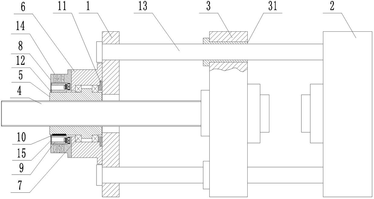
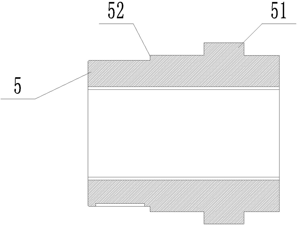
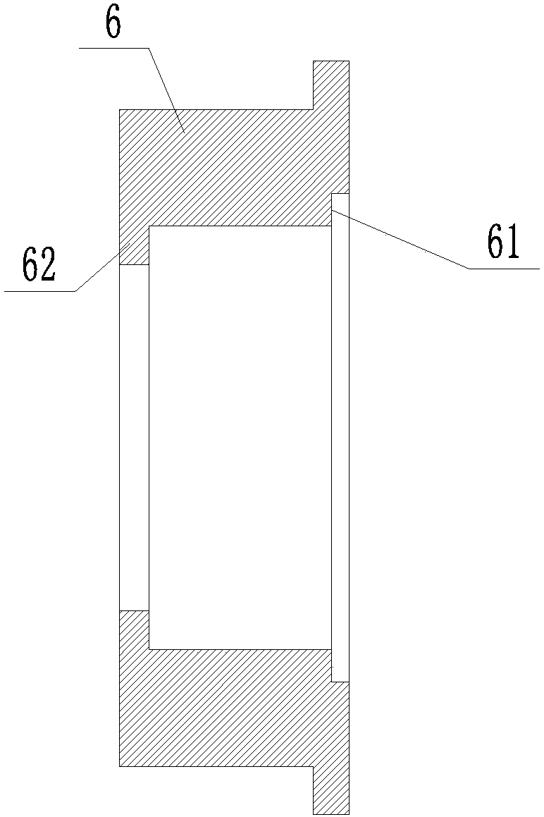
[0034] Such as Figure 1-8 As shown, a die-casting machine clamping mechanism directly driven by a frameless combined permanent magnet synchronous linear motor, the die-casting machine clamping mechanism includes a mounting plate 1, a guide post 13, a movable template 3 and a fixed template 2, the installation The plate 1 is connected to the fixed template 2 through the guide post 13; the movable template 3 is provided with a guide hole 31 adapted to the guide post, and is slidably connected to the guide post 13 through the guide hole 31 Above; the thrust screw 4 is fixedly connected to the movable template 3, and the thrust screw 4 is provided with a thrust by the rotation of the nut 5 fixed in the motor mount 6 through the bearing 7, and the motor mount 6 is fixed on the mounting plate 1; The nut 5 is directly driven by a frameless combined permanent magnet synchronous linear motor; the frameless combined permanent magnet synchronous linear motor includes a stator assembly 8...

Embodiment 2

[0039] Such as Figure 9-12 As shown, a die-casting machine clamping mechanism directly driven by a frameless combined permanent magnet synchronous linear motor, the die-casting machine clamping mechanism includes a mounting plate 1, a guide post 13, a movable template 3 and a fixed template 2, the installation The plate 1 is connected to the fixed template 2 through the guide post 13; the movable template 3 is provided with a guide hole 31 adapted to the guide post, and is slidably connected to the guide post 13 through the guide hole 31 Above; the thrust screw 4 is fixedly connected to the movable template 3, and the thrust screw 4 is provided with a thrust by the rotation of the nut 5 fixed in the motor mount 6 through the bearing 7, and the motor mount 6 is fixed on the mounting plate 1; The nut 5 is directly driven by a frameless combined permanent magnet synchronous linear motor; the frameless combined permanent magnet synchronous linear motor includes a stator assembly ...

Embodiment 3

[0044] Such as Figure 13 As shown, a die-casting machine clamping mechanism directly driven by a frameless combined permanent magnet synchronous linear motor, the die-casting machine clamping mechanism includes a mounting plate 1, a guide post 13, a movable template 3 and a fixed template 2, the installation The plate 1 is connected to the fixed template 2 through the guide post 13; the movable template 3 is provided with a guide hole 31 adapted to the guide post, and is slidably connected to the guide post 13 through the guide hole 31 Above; the thrust screw 4 is fixedly connected to the movable template 3, and the thrust screw 4 is provided with a thrust by the rotation of the nut 5 fixed in the motor mount 6 through the bearing 7, and the motor mount 6 is fixed on the mounting plate 1; The nut 5 is directly driven by a frameless combined permanent magnet synchronous linear motor; the frameless combined permanent magnet synchronous linear motor includes a stator assembly 8 ...


PUM


Abstract

The invention discloses a die locking mechanism for a die casting machine directly driven by a frameless combined type permanent magnet synchronous linear motor. The die locking mechanism for the diecasting machine comprises a mounting plate, guide columns, a movable die plate and a fixed die plate; the mounting plate is connected to the fixed die plate through the guide columns; guide holes matched with the guide columns are formed in the movable die plate, and the movable die plate is connected to the guide columns through the guide holes in a sliding manner; the movable die plate is fixedly connected to a thrust screw rod, and the thrust screw rod is used for providing thrust by rotation of a nut which is fixed on a motor mounting base through a bearing and is matched with the thrust screw rod, and the motor mounting base is fixed on the mounting plate; and the nut is directly driven by the frameless combined type permanent magnet synchronous linear motor. According to the die locking mechanism for the die casting machine directly driven by the frameless combined type permanent magnet synchronous linear motor, middle transmission parts are reduced, structure is simple, the transmission efficiency is high, and torque is large.

Description

technical field [0001] The invention relates to the technical field of workpiece processing equipment, in particular to a die-casting machine mold locking mechanism directly driven by a frameless combined permanent magnet synchronous linear motor. Background technique [0002] The die-casting machine is a series of industrial casting machines that hydraulically inject molten metal into the mold under pressure to cool and form it, and obtain solid metal castings after the mold is opened. It was originally used for die-casting characters. With the advancement of science and technology and industrial production, especially with the development of industries such as automobiles, motorcycles and household appliances, die-casting technology has developed extremely rapidly in various aspects. [0003] At present, there are more and more types of die-casting machines, more and more perfect functions, and more and more complex structures. As the core mechanism of die-casting machines...

Claims


Application Information

Patent Timeline
IPC IPC(8): B22D17/26H02K1/32H02K5/20H02K7/14H02K9/06H02K9/22H02K21/02H02K21/14
CPCH02K1/32H02K5/20H02K7/14H02K9/06H02K9/22H02K21/02H02K21/14B22D17/263
Inventor 黄诚杨勇强
Owner HUBEI HUANYEE ELECTROMAGNETIC EQUIP ENG TECH CO LTD
Why Eureka
Try Eureka