Continuous material guide device of efficient supplying drying equipment

A technology of drying equipment and material guide device, which is applied in the directions of packaging, transportation and packaging, loading/unloading, etc. It can solve the problems of poor sealing, high probability of impeller and valve body jamming, and short life of valve body, etc., and achieves The effect of stable connection, overcoming unstable connection, and overcoming high damage rate

Inactive Publication Date: 2018-06-22
章卓昕
View PDF1 Cites 0 Cited by
  • Summary
  • Abstract
  • Description
  • Claims
  • Application Information

AI Technical Summary

Problems solved by technology

In the existing impeller feeder, both ends of the blades are open, which easily causes friction between the material and the inner wall of the valve body, resulting in short service life of the valve body, poor sealing, etc., and the probability of material jamming between the impeller and the valve body is high. It is easy to cause failures such as shutdown and affect the normal operation of the feeder. In the prior art, for example, the invention patent with application number 201220566174.0 includes a valve body, a transmission shaft, blades and a geared motor. The valve body is welded into an integral structure with steel plates , a transmission shaft is installed on the valve body, and the transmission shaft is connected with the reduction motor, and the blade is rigidly connected with the transmission shaft to form an integrated rotating impeller, the blade is a V-shaped blade, and the two ends of the rotating impeller are respectively provided with a whole Circular stiffener structure, although the structure of the invention is simple, there are many deficiencies and defects. In the existing equipment, the design of the V-shaped blades has defects. When the V-shaped blades work continuously, part of the The materials will be missed during the movement and cause waste, and the V-shaped blades will chop the materials and cause damage to the materials during the rotation of the supply. In view of these situations, in order to avoid the above technical problems, it is necessary to provide a high-efficiency supply The continuous guide device of drying equipment to overcome the defects in the prior art

Method used


Image

  • Continuous material guide device of efficient supplying drying equipment
  • Continuous material guide device of efficient supplying drying equipment
  • Continuous material guide device of efficient supplying drying equipment

Examples


Embodiment Construction

[0023] The following will clearly and completely describe the technical solutions in the embodiments of the present invention with reference to the accompanying drawings in the embodiments of the present invention. Obviously, the described embodiments are only some, not all, embodiments of the present invention. Based on the embodiments of the present invention, all other embodiments obtained by persons of ordinary skill in the art without making creative efforts belong to the protection scope of the present invention.

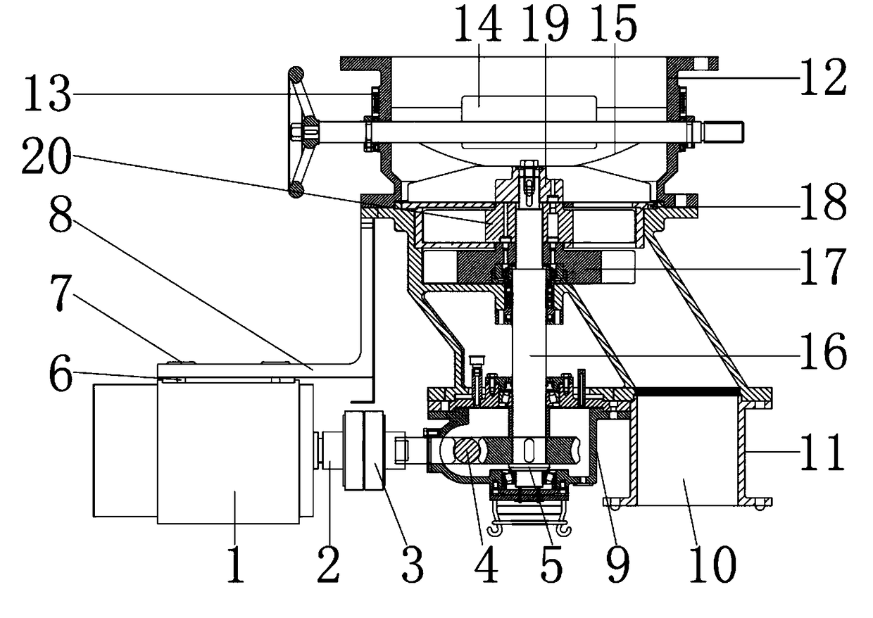
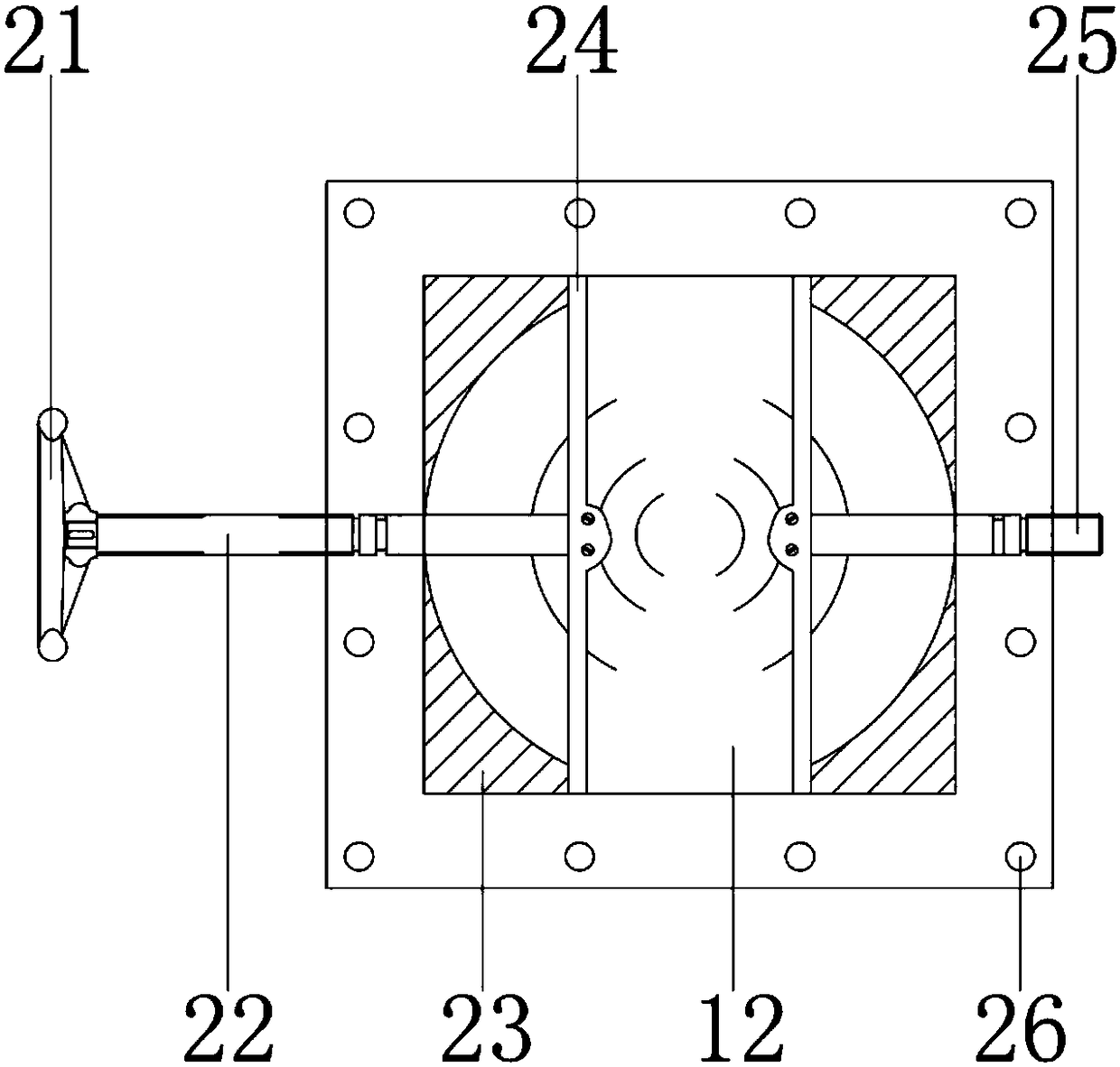
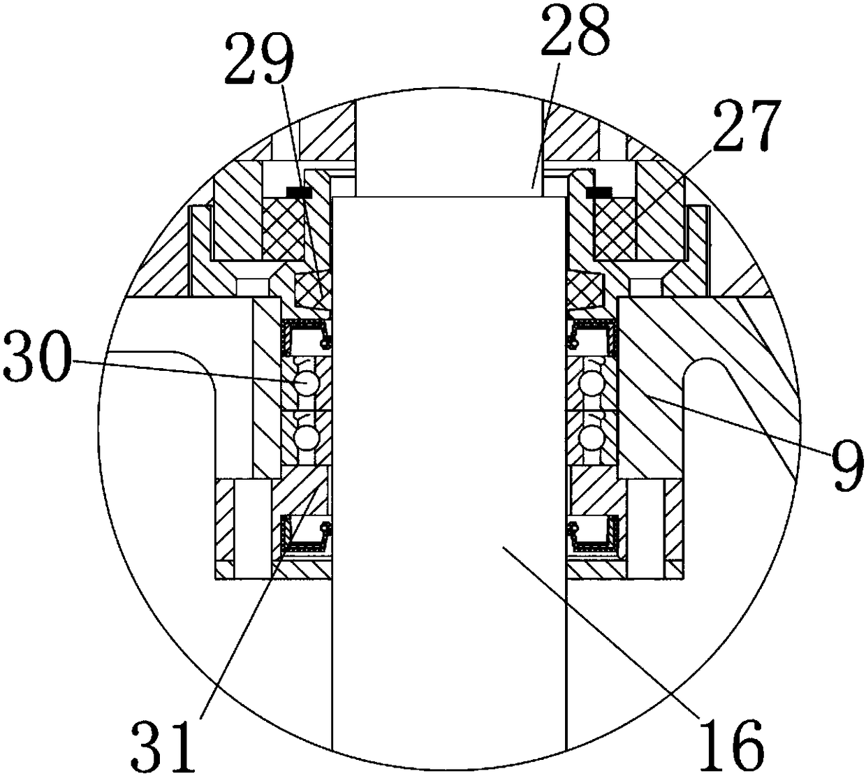
[0024] see Figure 1-4, the present invention provides a technical solution: a continuous material guide device for efficiently supplying drying equipment, including a motor 1, the motor 1 is an AC servo motor, the model is SDF-09L, and is used to control the speed of the main shaft 16 by adjusting the speed , the upper surface of the motor 1 is provided with a pad 6, the pad 6 is a rubber gasket, which is used to increase the friction and reduce the vibration...


PUM


Abstract

The invention discloses a continuous material guide device of efficient supplying drying equipment. The right side of a motor is provided with a rotary shaft; the inner wall of the rotary shaft is connected with the outer wall of a motor, and the right side of the rotary shaft is provided with a shaft connecting device; the inner wall of the shaft connecting device is connected with the outer wallof the rotary shaft, and the right side of the shaft connecting device is provided with a key shaft; and the outer wall of the key shaft is connected with the inner wall of the shaft connecting device, and the inner side of the key shaft is provided with a chain wheel. Through cooperation of the motor, a main rotary shaft and blades, the motor drives the main rotary shaft to rotate, the main rotary shaft can be accelerated by adjusting the rotation speed of the motor while rotating is conducted, and accordingly, the rotation speed of the blades can be increased; in order to avoid the situation that when materials are hung on the upper shell wall when falling down, a roller brush can clean the inner wall of an upper shell while the main rotary shaft is rotated, and accordingly, the defectsthat a traditional continuous material guide device of efficient supplying drying equipment is low in feeding efficiency, and the feeding rate is influenced due to the fact that too much materials are left on the inner wall of the upper shell are overcome.

Description

technical field [0001] The invention relates to the technical field of production machinery, in particular to a continuous material guide device for efficiently supplying drying equipment. Background technique [0002] The impeller feeder is used to continuously and evenly feed the dry powdery materials or small granular materials in the upper silo to the next equipment. It is a quantitative feeding equipment. In the existing impeller feeder, both ends of the blades are open, which easily causes friction between the material and the inner wall of the valve body, resulting in short service life of the valve body, poor sealing, etc., and the probability of material jamming between the impeller and the valve body is high. It is easy to cause failures such as shutdown and affect the normal operation of the feeder. In the prior art, for example, the invention patent with application number 201220566174.0 includes a valve body, a transmission shaft, blades and a geared motor. The ...

Claims


Application Information

Patent Timeline
Patent Type & Authority Applications(China)
IPC IPC(8): B65G65/48
CPCB65G65/4881B65G2207/32B65G2207/40
Inventor 章卓昕
Owner 章卓昕
Why Eureka
Try Eureka