Unlock instant, AI-driven research and patent intelligence for your innovation.

A projection-based rope fault detection method and device

A fault and rope-arranging technology, which is applied in the direction of measuring devices, hoisting devices, clockwork mechanisms, etc., can solve problems such as error-prone, low accuracy, low efficiency, etc., to eliminate optical distortion, improve light levels, improve reliability effect

Active Publication Date: 2019-04-09
CENT SOUTH UNIV
View PDF2 Cites 0 Cited by
  • Summary
  • Abstract
  • Description
  • Claims
  • Application Information

AI Technical Summary

Problems solved by technology

[0003] Existing methods for detecting faults in arranging ropes mostly use manual observation, which is inefficient and prone to errors when observed for a long time. CN201510025651.0 proposes a method and system for detecting faults in drum wire rope arranging faults based on machine vision, which uses an industrial camera , The way of image processing partly makes up for the blank of intelligent rope fault detection, but the image is detected from the direction of the plane, which has poor adaptability to the transition between layers, unsatisfactory lighting, and changes in the industrial control environment
CN201210365602.8 proposes a control method, system and engineering machinery for reel anti-disorder rope, and proposes a binary method for image processing. Although it reduces the amount of calculation and simplifies the processing flow, it still adopts the method of image acquisition. The method of shooting the original roll with a special camera, and this method will be due to optical distortion in actual use, such as shooting the surface from a point, the closer the image is, the larger the image is, the farther the image is, the smaller the image is, and the final image The straight lines of the edges are significantly curved, thus leading to inaccurate conclusions drawn by the described method

Method used


Image

  • A projection-based rope fault detection method and device
  • A projection-based rope fault detection method and device
  • A projection-based rope fault detection method and device

Examples


Embodiment Construction

[0043] The present invention will be further described below in conjunction with examples.

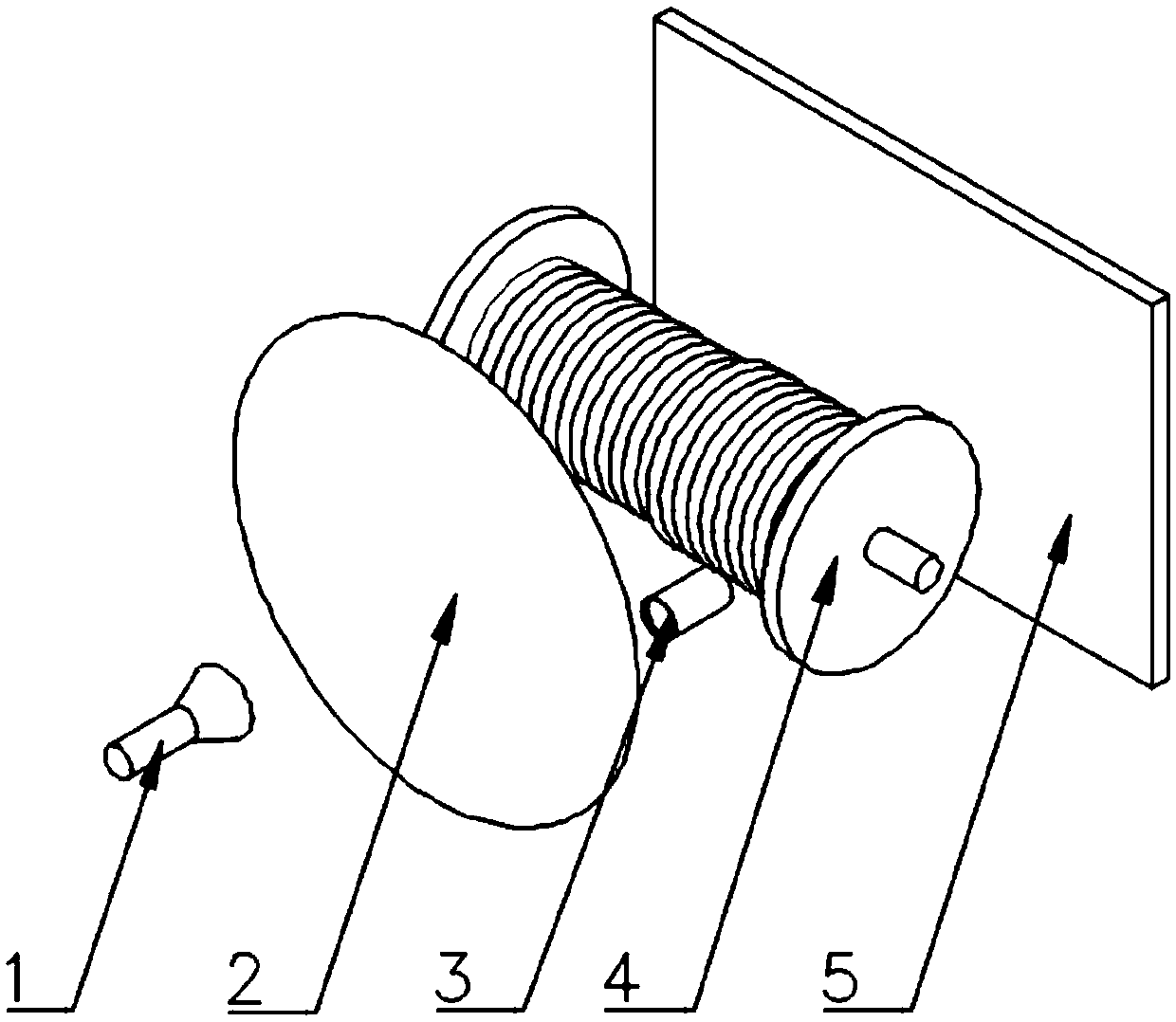
[0044] Such as figure 1 and figure 2 As shown, a projection-based rope arrangement fault detection device includes a single-point light source 1, a convex lens 2, a reel 4, a camera 3, and a white base plate 5, and the single-point light source 1, convex lens 2, reel 4, and white base plate 5 are all connected to each other. Set in parallel with each center at the same level. Among them, the single-point light source 1 and the reel 4 are arranged on both sides of the convex lens 2, the single-point light source 1 is located at the focus position of the convex lens 2, the reel 4 is arranged between the convex lens 2 and the white base plate 5, and the winding rope is arranged on the reel 4 , the camera and the reel 4 are located on the same side of the white base 5 , and the shooting direction of the camera is perpendicular to the white base 5 . Through the above-mentioned device, t...


PUM


Abstract

The invention discloses a rope arrangement fault detection method based on projection and a device applying the same. The method comprises the steps of 1, illuminating a winding drum through parallellight, and shooting projection, on a white base plate, of the winding drum through a video camera, so that a projected image is obtained; 2, conducting binarization processing on the projected image obtained in step 1, and building two-dimensional coordinates of the image; 3, according to the pixel distance between the central line of a winding rope on each layer and the outer disc face of the winding drum, obtaining arrays of the winding ropes of all the layers in the projected image formed after processing in step 2 is completed; 4, grouping adjacent pixel points, with the grey level being Z, in each array into a zone, conducting statistics on the zone number of each array, and obtaining the length of each zone; and 5, according to the number of the zones contained in each array and thelength of each zone obtained in step 4, drawing a winding drum rope arrangement fault conclusion.By means of the method, the more precise rope arrangement fault conclusion can be obtained.

Description

technical field [0001] The invention belongs to the field of fault detection of reel winding and arranging ropes on industrial sites, and in particular relates to a method and device for detecting faults in arranging ropes based on projection. Background technique [0002] Underground resource mining is mostly using mine hoisting equipment. With the advancement of science and technology and the continuous improvement of mine production modernization requirements, more and more attention has been paid to improving the operation stability and safety of equipment. Improving equipment informatization and intelligent transformation are mine hoisting equipment. The most important thing to upgrade. [0003] Existing methods for detecting faults in arranging ropes mostly use manual observation, which is inefficient and prone to errors when observed for a long time. CN201510025651.0 proposes a method and system for detecting faults in drum wire rope arranging faults based on machine ...

Claims


Application Information

Patent Timeline
Patent Type & Authority Patents(China)
IPC IPC(8): B66D1/54G01N21/89
CPCB66D1/54G01N21/8914
Inventor 谭建平石理想薛少华王巧斌
Owner CENT SOUTH UNIV
Features
  • R&D
  • Intellectual Property
  • Life Sciences
  • Materials
  • Tech Scout
  • Unparalleled Data Quality
  • Higher Quality Content
  • 60% Fewer Hallucinations
Learn More