Unlock instant, AI-driven research and patent intelligence for your innovation.

Standard gas generation system and method for calibrating or verifying exhaust-gas telemetry system

A generation system and telemetry system technology, applied in the field of standard gas generation system, can solve the problems of reducing detection accuracy, deviation of system detection results, inability to simulate exhaust gas diffusion, etc., achieving real-time calibration and verification, and improving measurement accuracy. Effect

Inactive Publication Date: 2018-06-22
BEIJING SDL TECH
View PDF8 Cites 3 Cited by
  • Summary
  • Abstract
  • Description
  • Claims
  • Application Information

AI Technical Summary

Problems solved by technology

[0006] Only the detection instrument can be calibrated, but the entire measurement system cannot be calibrated and verified;
[0007] It is impossible to truly simulate the actual emission of motor vehicle exhaust, and it is impossible to prepare various concentrations of standard gas according to different emission conditions of motor vehicle exhaust. It is only possible to simply calibrate the range of the analyzer, and it is impossible to verify the effectiveness of the system. Thereby reducing the reliability of the vehicle exhaust telemetry system
[0008] It is impossible to simulate the actual operation of motor vehicles, different motor vehicle speeds, different running trajectories, and system detection results have deviations, thereby reducing the accuracy of detection;
[0009] It is impossible to simulate the real diffusion of exhaust gas and the measurement results are different when the exhaust gas is in different positions of the telemetry system during measurement

Method used


Image

  • Standard gas generation system and method for calibrating or verifying exhaust-gas telemetry system

Examples


Embodiment

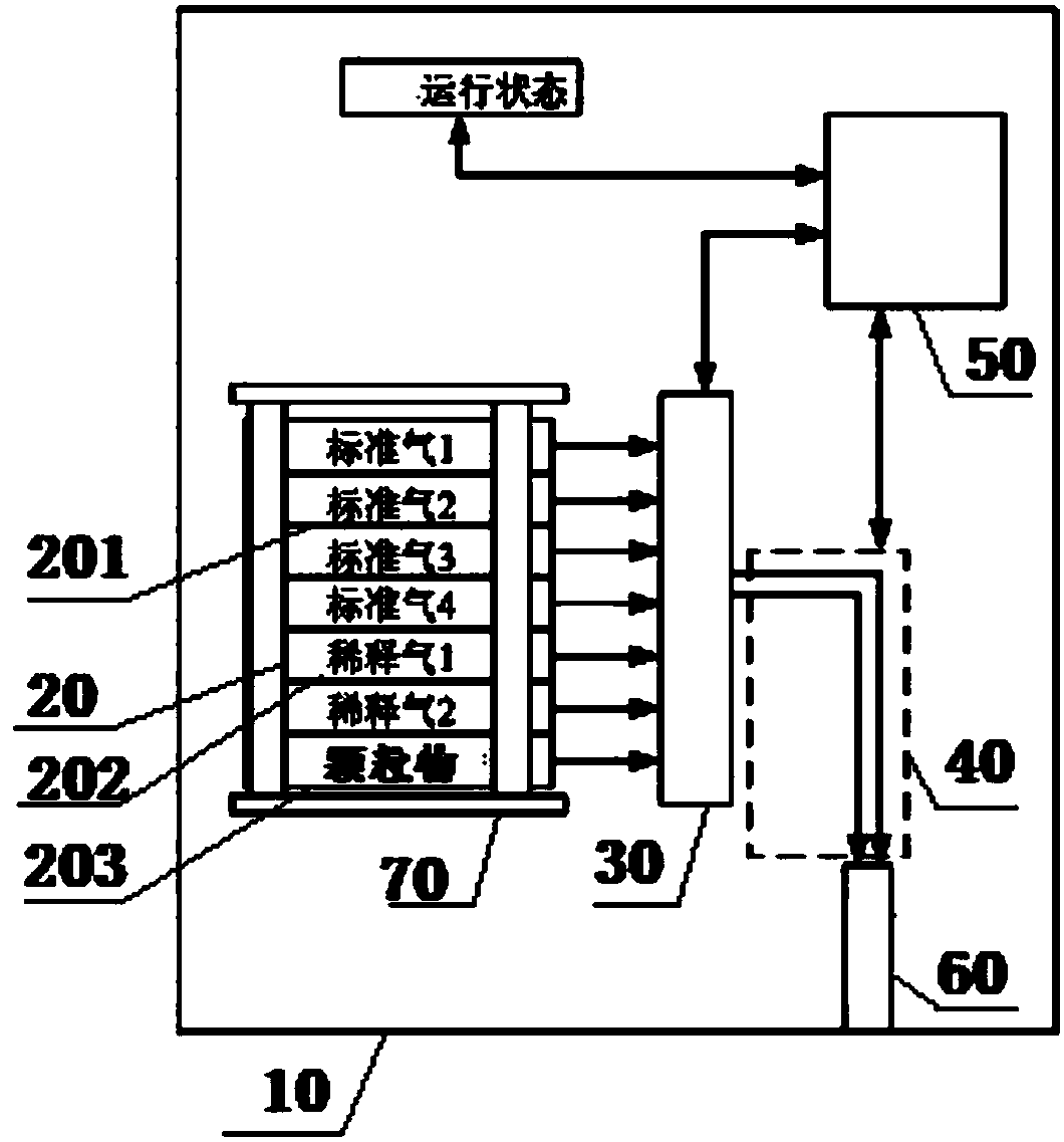
[0053] The basic composition of this embodiment scheme, such as figure 1 As shown: the motion simulation device 10 is realized by a truck, and additionally includes a gas cylinder fixing bracket 70, a standard gas device 201, a dilution gas generator 202, a particulate matter generator 203, a multi-channel mass flow controller 30, and a heating module 40 as a heating pipeline. The air position adjustable device 60 is an exhaust tube, the truck running state recording module, and the system control module 50 is a system control computer.

[0054] The truck is driven by electricity, and its own exhaust pipe should be modified. When performing calibration, calibration, and verifying the motor vehicle exhaust remote measurement system, it can discharge its own exhaust gas to a far distance by switching the switch, which is not good for the standard gas generation system. interfere. The truck itself can run at different speeds, accelerations and trajectories, and can provide compr...


PUM


Abstract

The invention relates to a standard gas generation system and method for calibrating or verifying an exhaust-gas telemetry system. The standard gas generation system comprises a motion simulation device, a gas distribution module, a multi-channel mass flow controller and a heating module, wherein the gas distribution module is used for generating original input gas for standard gas; the multi-channel mass flow controller is used for performing flow control on the original input gas so as to output a gas mixture with a desired concentration; the heating module is used for heating control of thegas mixture so as to output standard gas; the gas distribution module, the multi-channel mass flow controller and the heating module are sequentially connected; and the gas distribution module, the multi-channel mass flow controller and the heating module are all arranged on the motion simulation device. The standard gas generation system of the invention can simulate the operation of a to-be-tested motor vehicle according to a preset speed, a preset accelerated speed and a preset trajectory, and the gas distribution and control module can perform gas distribution according to preset parameters such as concentration, displacement and temperature, so the standard gas generation system can accurately carry out on-line and real-time calibration and verification of the exhaust-gas telemetry system of the motor vehicle.

Description

technical field [0001] The invention relates to the technical field of tail gas remote measurement system calibration, in particular to a standard gas generating system for calibrating or verifying the tail gas remote measuring system and methods for generating, calibrating and verifying. Background technique [0002] In order to control the emissions of motor vehicle exhaust pollutants, the state has issued a series of environmental protection standards, including the recently issued "Measuring Methods and Technical Requirements for Exhaust Pollutants of Diesel Vehicles in Use (Remote Sensing Detection Method)" (HJ845-2017 ). The standard stipulates the method of long-distance sensing and measuring the exhaust pollutants of driving motor vehicles by using optical principles. The motor vehicle exhaust gas measurement components specified in the standard include: CO, CO2, NO, CH (total hydrocarbons), particulate matter concentration and other parameters, and in some local st...

Claims


Application Information

Patent Timeline
IPC IPC(8): G01N21/17G01N21/27
CPCG01N21/17G01N21/274G01N2021/1793
Inventor 曹乃玉郜武刘利石磊
Owner BEIJING SDL TECH
Features
  • R&D
  • Intellectual Property
  • Life Sciences
  • Materials
  • Tech Scout
  • Unparalleled Data Quality
  • Higher Quality Content
  • 60% Fewer Hallucinations
Learn More