
Improved light guide plate

A technology of light guide plate and light guide point, which is applied to the dispersed propagation of geometric optics and the field of light guide plate, which can solve the problems of poor surface roughness of light guide plate, uneven light output from light guide plate, and inability to cut the finished product at will, so as to shorten the production cycle , high luminous efficiency, easy to implement effect

Active Publication Date: 2018-06-22
佛山市德联邦盛光电科技股份有限公司
View PDF6 Cites 0 Cited by
  • Summary
  • Abstract
  • Description
  • Claims
  • Application Information

AI Technical Summary

Problems solved by technology

[0004] Although the laser-engraved light guide plate can be made in a whole plate, cut and used at will, or can be made in a special plate with individual specifications, but the efficiency is very low, the defect rate is high, the production cycle is long, and it is not convenient for mass production
[0005] V-shaped cross grid engraving: Coat a flat silicon wafer with a layer of corrosion-resistant photoresist, then let strong light pass through the photoresist plate, and perform selective selection on the photoresist plate according to the graphic information of the specific layer produced Then, the developed photoresist is removed, and a thin film with a micro-pattern structure will be left on the upper surface of the silicon wafer. The surface roughness of the light guide plate made by photolithography is not good, and the loss of light energy is relatively large.
[0006] UV screen printing: Each specification of the light guide plate must be plate-made separately, and the finished product cannot be cut at will, so there are shortcomings in the application
[0007] Traditional process injection molding: A transparent particle material with scattering function that is directly injected into the light guide plate during injection molding of the light guide plate. By adjusting the concentration of transparent particles reasonably, the effective control of the light output can be achieved, and finally the high uniformity of the light output can be achieved. Due to The doping process is not easy to control accurately, so the injection molding method is suitable for making small and medium-sized light guide plates. For large-sized light guide plates, there will be uneven light output.

Method used


Image

  • Improved light guide plate
  • Improved light guide plate
  • Improved light guide plate

Examples


Embodiment 1

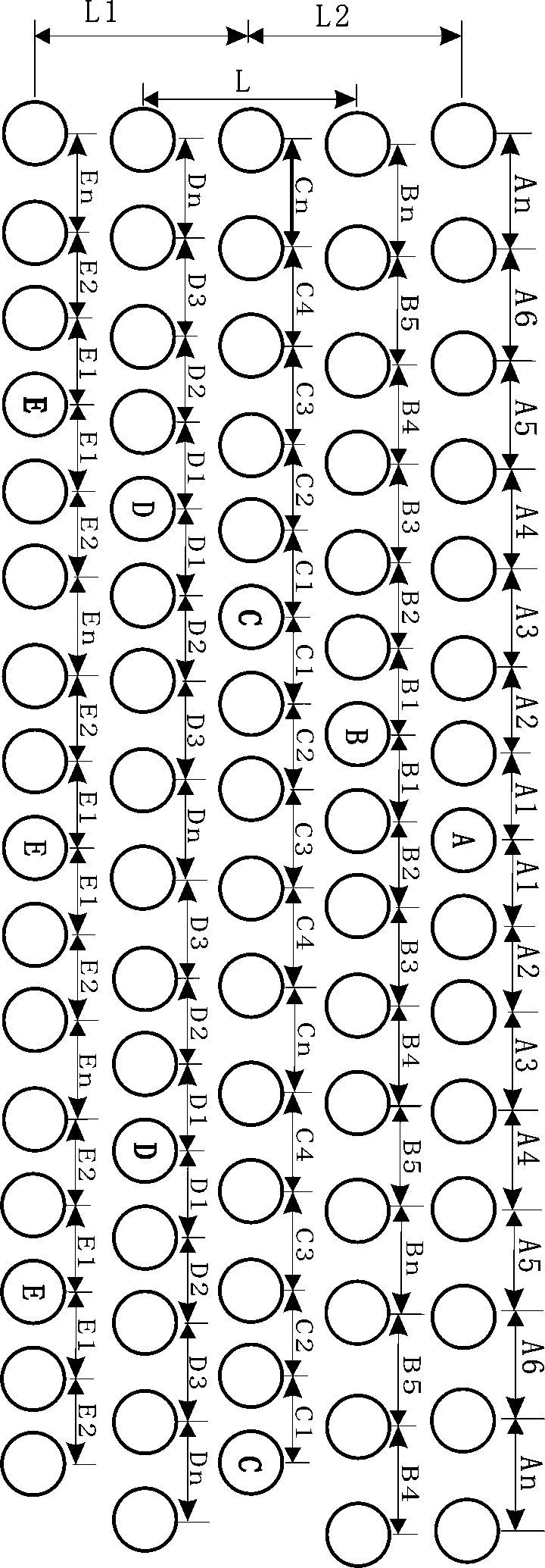
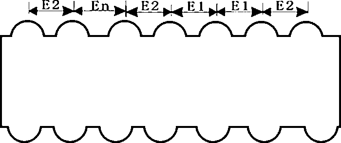
[0025] Implement 1, such as Figure 1-2 As shown, the front and back sides of the light guide plate are composed of two groups of asymmetric convex-sphere-shaped light guide points, and the two groups change according to the following rules:

[0026] The light guide points are arranged in five groups of ABCDE to form a small unit. The group E takes the light guide point E as the middle light guide point, and the distance between the light guide points on both sides of the light guide point E is larger than the other E1<E2<En, After reaching the distance En, they are reversely arranged from En to E1, and the circular arrangement is repeated in this way. Similarly, each group of BCDE uses the light guide point BCDE as the intermediate light guide point and repeats the circular arrangement in this way; The distance between the two light guide points of the sequence number is equal, that is, E1=D1=C1=B1=A1, E2=D2=C2=B2=B2, and the number of light guide points in each group of ligh...

Embodiment 2

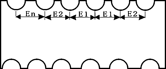
[0028] Implement 2, such as figure 1 , 3 As shown, the front and back sides of the light guide plate are composed of two groups of asymmetric concave spherical light guide points, and the two groups change according to the following rules:

[0029] The light guide points are arranged in five groups of ABCDE to form a small unit. The group E takes the light guide point E as the middle light guide point, and the distance between the light guide points on both sides of the light guide point E is larger than the other E1<E2<En, After reaching the distance En, they are reversely arranged from En to E1, and the circular arrangement is repeated in this way. Similarly, each group of BCDE uses the light guide point BCDE as the intermediate light guide point and repeats the circular arrangement in this way; The distance between the two light guide points of the sequence number is equal, that is, E1=D1=C1=B1=A1, E2=D2=C2=B2=B2, and the number of light guide points in each group of light...

Embodiment 3

[0031] Implementation 3, implementation 2, such as figure 1 , 4 As shown, the front side of the light guide plate is a group of convex-spherical-shaped light-guiding points, and the back is a group of concave-spherical-shaped light-guiding points, and the two groups change according to the following rules:

[0032] The light guide points are arranged in five groups of ABCDE to form a small unit. The group E takes the light guide point E as the middle light guide point, and the distance between the light guide points on both sides of the light guide point E is larger than the other E1<E2<En, After reaching the distance En, they are reversely arranged from En to E1, and the circular arrangement is repeated in this way. Similarly, each group of BCDE uses the light guide point BCDE as the intermediate light guide point and repeats the circular arrangement in this way; The distance between the two light guide points of the sequence number is equal, that is, E1=D1=C1=B1=A1, E2=D2=C...


PUM

PropertyMeasurementUnit
Bottom diameteraaaaaaaaaa

Abstract

The invention discloses an improved light guide plate, relates to the field of disperse propagation of geometrical optics, and especially relates to the technical field of a light guide plate. The improved light guide plate is characterized in that the surfaces of the light guide plate are provided with spherical-segment-shaped light guide points with gradient distance, wherein the light guide points are in convex spherical segment shape or in concave spherical segment shape; the light guide points are same in size; the light guide points are arranged in at least five groups; each group of light guide points are arranged in a line; each group of light guide points at least has one middle light guide point; the distance between the light guide points at the two sides of the middle light guide point increases gradually to a certain distance, and then, decreases gradually, and the light guide points are in such repeated cycle arrangement; the number of light guide points changing gradually at the two sides is different from group to group, and the middle light guide point is different in position; and the distance between two light guide points same in arrangement number and startingfrom the middle light guide points in all groups is same. The improved light guide plate can be directly extruded and moulded, and can be directly cut and used without carrying out dotting or silkscreen processing on the surface, thereby reducing production cost, reducing reject ratio, reducing production period and enabling luminous efficiency to be stronger and more uniform.

Description

technical field [0001] The invention relates to the field of dispersion propagation of geometric optics, in particular to the technical field of light guide plates. Background technique [0002] The light guide plate is made of optical-grade acrylic / PC board, and then high-tech materials with high reflectivity and non-absorbing light are used. It is a high-tech product that transforms line light sources into surface light sources. [0003] The light guide plate in the current technology is used in various displays, such as LED flat panel lights, flat panel displays and backlight modules of TVs. The light guide plate is generally made of acrylic / PC board, and the light incident point is set on one side of the light guide plate or Surroundings, the light source is refracted and scattered through concave and convex points, making the light source soft and uniform. The traditional processing technology prints light guide points on a flat substrate by laser engraving, V-shaped cr...

Claims


Application Information

Patent Timeline
IPC IPC(8): G02B6/00
CPCG02B6/0036G02B6/0058
Inventor 袁志华谭炳幸
Owner 佛山市德联邦盛光电科技股份有限公司
Features
  • Generate Ideas
  • Intellectual Property
  • Life Sciences
  • Materials
  • Tech Scout
  • Unparalleled Data Quality
  • Higher Quality Content
  • 60% Fewer Hallucinations
Learn More