Cylindrical cutter upset-extruding molding method

A forming method and a technology of cylindrical cutters, which are applied to knives, household utensils, kitchen utensils, etc., can solve problems such as polluting the environment, affecting the life of knives, and generating smoke, and achieve the effects of reducing skill requirements, improving the life of knives, and improving precision

Inactive Publication Date: 2015-05-27
许自清
View PDF7 Cites 0 Cited by
  • Summary
  • Abstract
  • Description
  • Claims
  • Application Information

AI Technical Summary

Problems solved by technology

[0003] 1. Smoke is generated during welding, the production environment is poor, harmful to health, and pollutes the environment at the same time;
[0004] 2. The tool causes annealing and cracks at high temperature, and shrinks during cooling to generate stress, which affects the life of the tool;
[0005] 3. The welding process consumes heavy metal wires, solvents and high energy consumption, requiring manual positioning operations, low work efficiency, poor working conditions, and high requirements for welder skills;
[0006] 4. After welding, the shape and position tolerance is relatively large, and the precision of the product head is not high

Method used


Image

  • Cylindrical cutter upset-extruding molding method
  • Cylindrical cutter upset-extruding molding method
  • Cylindrical cutter upset-extruding molding method

Examples


Embodiment 1

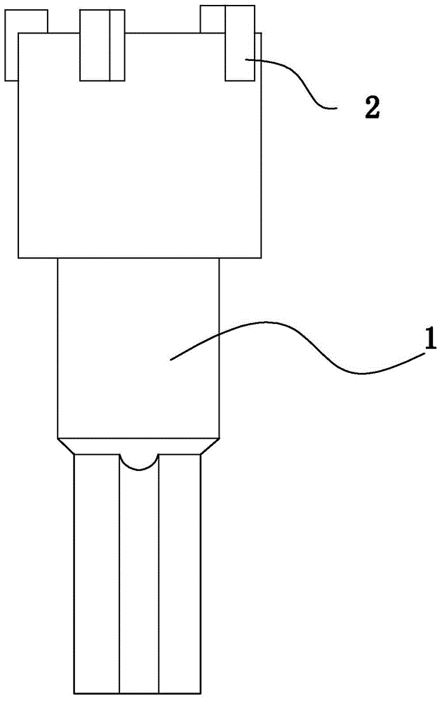
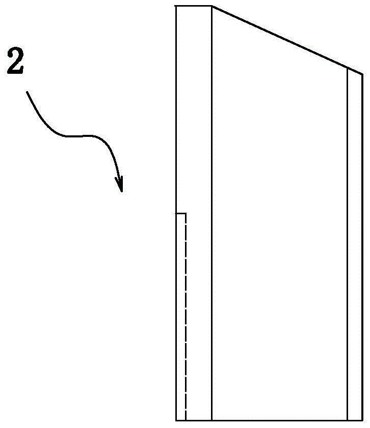
[0033] Such as Figure 1-4 As shown, a method of upsetting and extruding a tubular cutter includes the following steps: preprocessing of the cutter head 2; positioning of the cutter body 1; assembly of the cutter head 2; and upsetting and extrusion forming. The cutter head 2 is a terrace whose bottom diameter is larger than that of the head. The terrace structure is beneficial to control the material flow during upsetting, so that the cutter head and the groove of the cutter body are closely combined and seamlessly connected. The terrace structure can be diversified, see Embodiment 4-8 for details.

[0034] The edge of the head of the cutter head 2 is asymmetrically arranged, and the width of the left edge 22 is smaller than the width of the right edge 23 . At the same time, the length of the left slope 24 is greater than that of the right slope 26, which is conducive to chip removal. This structure reduces the size of the cutter head, about one-sixth of the amount of common...

Embodiment 2

[0036] The difference from Embodiment 1 is that the cutter head 2 has a concave arc-shaped waist 27 at the bottom. The waist is designed for easy positioning between the cutter head and the groove of the cutter body.

Embodiment 3

[0038] Different from Example 1, as Figure 6 As shown, the bottom of the cutter head 2 has an indented portion 28 and a corresponding convex portion 29 . This structure is conducive to positioning, and at the same time, it will not cause damage to the mechanical structure of the cutter head.

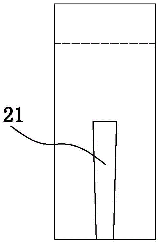
[0039] At least one rectangular groove 21 is opened in the middle of the cutter head.


PUM


Abstract

The invention relates to a cylindrical cutter upset-extruding molding method. Extruding is utilized to replace brazing, or a cemented cutter is adopted. A press machine is adopted to compress a cutter body to enable the cutter body to have radial and axial plastic deformation. Mechanical biting force is utilized to achieve connection of the cutter body and a hard alloy cutter bit to achieve the advantages of simple process method, high accuracy, high production speed, low labor intensity, no pollution in the manufacturing process and the like.

Description

technical field [0001] The invention relates to a processing method of a cylindrical cutter, in particular to an upsetting extrusion forming method of a cylindrical cutter. Background technique [0002] The commercially available cylindrical cutter includes a cutter body and a cutter head, and the cutter head is fixed by oxyacetylene welding. The problems in this process are: [0003] 1. Smoke is generated during welding, the production environment is poor, harmful to health, and pollutes the environment at the same time; [0004] 2. The tool causes annealing and cracks at high temperature, and shrinks during cooling to generate stress, which affects the life of the tool; [0005] 3. The welding process consumes heavy metal wires, solvents and high energy consumption, requiring manual positioning operations, low work efficiency, poor working conditions, and high requirements for welder skills; [0006] 4. After welding, the shape and position tolerance is relatively large,...

Claims


Application Information

Patent Timeline
Patent Type & Authority Applications(China)
IPC IPC(8): B21K11/02
Inventor 许自清
Owner 许自清
Why Eureka
Try Eureka