Automatic laser cleaning device used for cleaning aircraft parts

A technology for laser cleaning and parts, applied in the direction of cleaning methods and appliances, chemical instruments and methods, etc., can solve the problems of low efficiency, long processing time, etc., achieve short adjustment time, fast response, and avoid repeated cleaning processes Effect

Pending Publication Date: 2018-06-26
彭州启光科技有限公司
View PDF10 Cites 6 Cited by
  • Summary
  • Abstract
  • Description
  • Claims
  • Application Information

AI Technical Summary

Problems solved by technology

[0004] Aiming at the deficiencies in the prior art, the present invention provides an automatic laser cleaning device for cleaning aircraft parts, which solves the problem of the laser cleaning device in the prior art when the laser is adjusted to hit the rust-removing aircraft parts. The size and position of the generated light spot are manually adjusted, resulting in long processing time and low efficiency.

Method used


Image

  • Automatic laser cleaning device used for cleaning aircraft parts
  • Automatic laser cleaning device used for cleaning aircraft parts
  • Automatic laser cleaning device used for cleaning aircraft parts

Examples


Embodiment Construction

[0015] The present invention will be further described below in conjunction with the accompanying drawings.

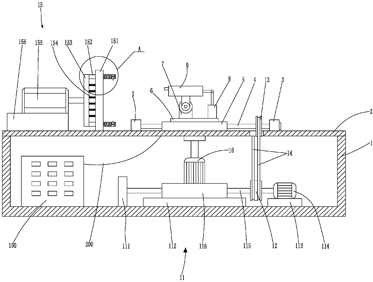
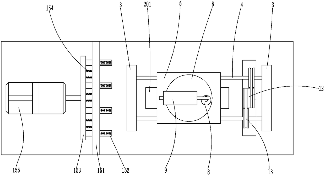
[0016] like Figure 1 ~ Figure 3 As shown, a kind of automatic laser cleaning device for aircraft parts cleaning according to the present invention includes an open base 1, the base 1 is a cuboid structure and the support plate 2 is fixed on the base 1, the base 1 1 is equipped with a laser generator 100, a rectangular hole 201 is opened on the support plate 2 along its length direction, two positioning blocks 3 are respectively located outside the short sides of the rectangular hole 201 on the support plate 2, and the two positioning blocks 3 There are two parallel first screw rods 4 for rotation between them. The two first screw rods 4 are threaded with a sliding seat 5 that is slidingly matched with the support plate 2. Through the rotation of the two first screw rods 4, the sliding The seat 5 moves laterally on the support plate 2 . A rotating disk 6 with a "T" s...


PUM


Abstract

The invention provides an automatic laser cleaning device used for cleaning aircraft parts. The automatic laser cleaning device comprises an open machine base. A supporting plate is fixedly connectedto the machine base. A rectangular hole is formed in the supporting plate. Two positioning blocks located outside the rectangular hole are arranged on the supporting plate. Two parallel first lead screws are rotatably arranged between the two positioning blocks. A sliding base in sliding fit with the supporting plate is arranged on the two first lead screws in a threaded fit mode. A rotary disc isrotatably arranged on the sliding base. A rotary base and a vertical hydraulic cylinder are fixedly connected to the rotary disc. A laser cleaning head connected with a laser generator through an optical fiber is rotatably arranged on the rotary base. The tail end of the laser cleaning head is rotatably connected with a piston rod of a vertical hydraulic cylinder. The rotary disc stretches into the machine base and is connected with a first driving motor. A driving mechanism used for driving the first driving motor and the sliding base to synchronously move is arranged in the machine base. Apositioning tool is further arranged on the supporting plate. The position and swinging of the laser cleaning head are controlled automatically, and the spot size of laser irradiated on an object is controlled, so that the adjustment time is short, and the response speed is high.

Description

technical field [0001] The invention relates to the technical field of cleaning equipment for aircraft parts, in particular to an automatic laser cleaning device for cleaning aircraft parts. Background technique [0002] There are several parts in the aircraft. In order to have anti-corrosion properties, the aircraft parts or the outer surface of the aircraft are painted on the surface of the aircraft parts or the outer surface of the aircraft to avoid corrosion. Paint stripping is required for maintenance and overhaul to ensure the reliability of the aircraft. The paint stripper method currently used not only pollutes the environment, damages the health of the operator, but is also expensive, and cannot guarantee that the aircraft parts can still be used normally after the paint is stripped , it is easy to cause aircraft parts to be scrapped. In order to overcome the disadvantages of this cleaning method, a laser cleaning device is used to clean the paint on aircraft parts,...

Claims


Application Information

Patent Timeline
Patent Type & Authority Applications(China)
IPC IPC(8): B08B7/00B08B13/00
CPCB08B7/0042B08B13/00
Inventor 汪树兵
Owner 彭州启光科技有限公司
Why Eureka
Try Eureka