
Grounding switch state monitoring device

A grounding knife and detector technology, applied in the field of smart grid, can solve problems such as inability to monitor the state of the grounding knife, and achieve the effect of accurate and reliable grounding knife state results and easy installation.

Inactive Publication Date: 2018-06-26
CHINA PETROLEUM & CHEM CORP +1
View PDF7 Cites 0 Cited by
  • Summary
  • Abstract
  • Description
  • Claims
  • Application Information

AI Technical Summary

Problems solved by technology

[0003] The existing grounding knife state monitoring devices usually use current detection or proximity switches to monitor the state of the grounding knife. However, these devices have many problems and cannot monitor the state of the grounding knife accurately and reliably.

Method used


Image

  • Grounding switch state monitoring device
  • Grounding switch state monitoring device
  • Grounding switch state monitoring device

Examples


Embodiment Construction

[0030] The implementation of the present invention will be described in detail below in conjunction with the accompanying drawings and examples, so as to fully understand and implement the process of how to apply technical means to solve technical problems and achieve technical effects in the present invention. It should be noted that, as long as there is no conflict, each embodiment and each feature in each embodiment of the present invention can be combined with each other, and the formed technical solutions are all within the protection scope of the present invention.

[0031] Also, in the following description, for purposes of explanation, numerous specific details are set forth in order to provide a thorough understanding of embodiments of the invention. It will be apparent, however, to one skilled in the art that the present invention may be practiced without the specific details or in the particular manner described.

[0032] For the existing device that uses a temperat...


PUM


Abstract

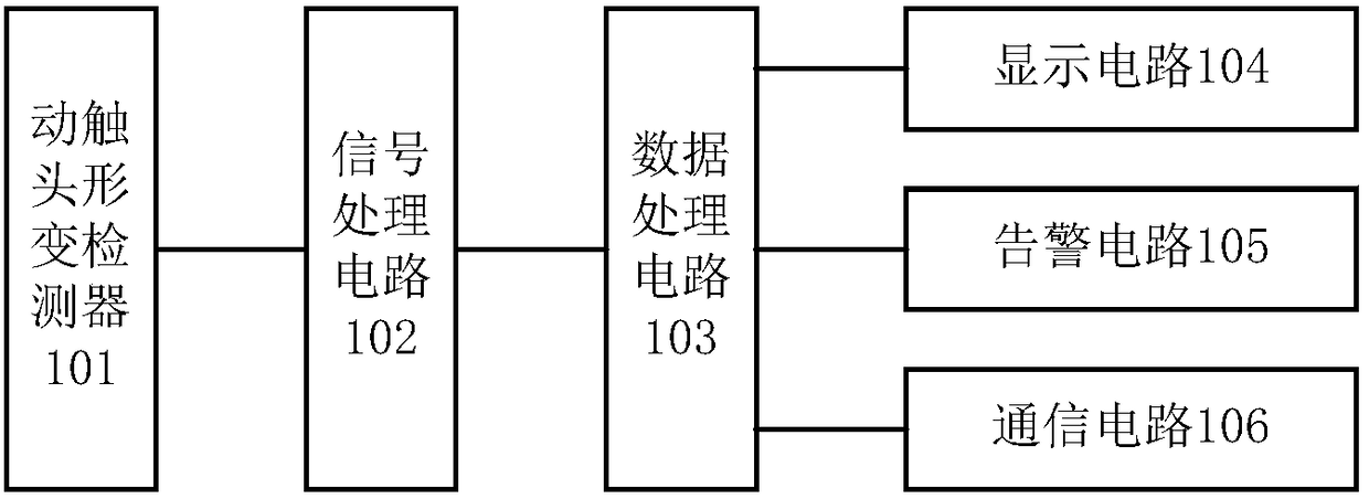
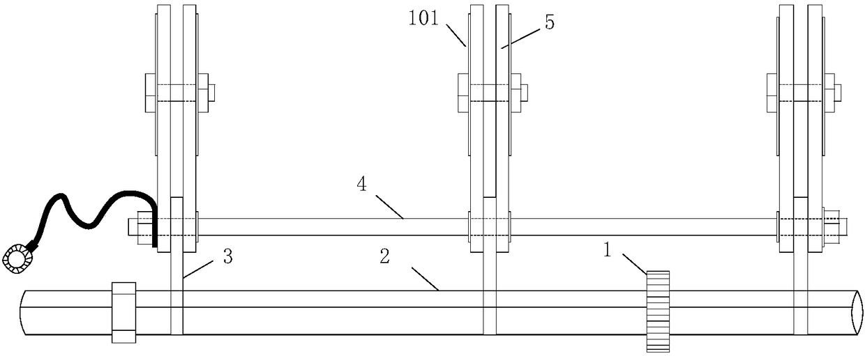
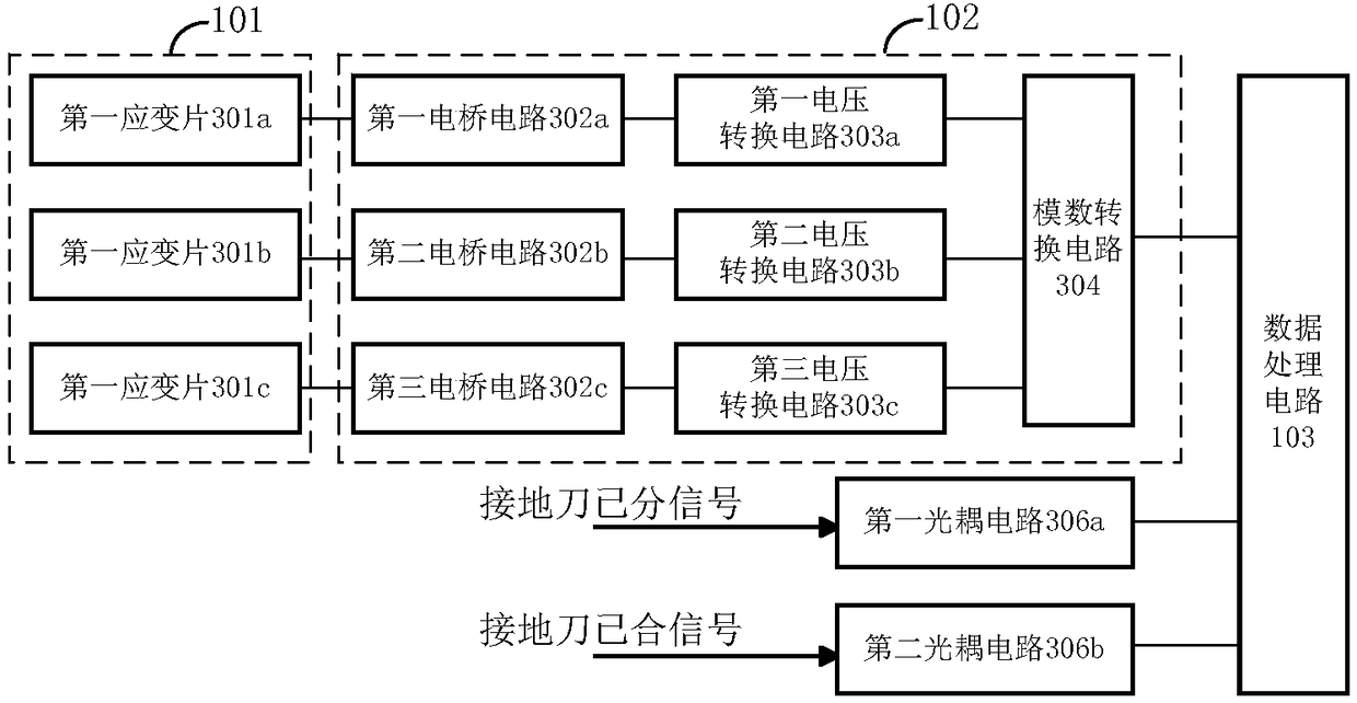
A grounding switch state monitoring device comprises a moving contact deformation detector, a signal processing circuit and a data processing circuit; the moving contact deformation detector detects deformation of a moving contact of a grounding switch to obtain a moving contact deformation signal; the signal processing circuit is connected with the moving contact deformation detector, and processes the moving contact deformation signal to obtain a first electrical signal; and the data processing circuit is connected with the signal processing circuit, and generates a grounding switch state signal for representing the opening / closing state of the grounding switch according to the first electric signal. The monitoring device uses the moving contact deformation detector to detect deformation, caused by extrusion of a static contact, of the moving contact directly instead of detecting the contact state between the moving contact and the static contact of the grounding switch indirectly asin present devices, and thus, the opening / closing state of the grounding switch and the contact between the static and moving contacts can be reflected directly. Compared with a present grounding switch state monitoring device, the monitoring device of the invention can obtain a more accurate and reliable grounding switch state result.

Description

technical field [0001] The invention relates to the technical field of smart grids, in particular to a grounding knife state monitoring device. Background technique [0002] With the vigorous development of my country's smart grid, the grounding knife is a large number of equipment in the operation of the grid, and it is also a primary high-voltage equipment that generates more faults. Although the structure of the grounding knife is relatively simple, due to the influence of the operating environment and climate conditions, as well as design and manufacturing, long-term operation is likely to cause poor contact, wear, and deformation, which will affect the safe and reliable operation of the power grid and cause unnecessary safety incidents. Therefore, the on-line monitoring of the reliability action of the grounding knife of the switchgear is particularly important. [0003] The existing grounding knife state monitoring devices usually use current detection or proximity s...

Claims


Application Information

Patent Timeline
Patent Type & Authority Applications(China)
IPC IPC(8): G01R31/04G01B7/16
CPCG01B7/18G01R31/66
Inventor 胡海燕刘全桢王世强黄新波张云朋朱永灿肖睿刘英杰
Owner CHINA PETROLEUM & CHEM CORP
Learn More