Wireless charging system for electronic device

A technology of wireless charging and electronic equipment, applied in the direction of electrical components, circuit devices, etc., can solve the problems of static loss at the sending end, poor practicability, waste of resources, etc., and achieve the effects of reducing static loss, improving charging efficiency, and extending service life

Inactive Publication Date: 2018-06-26
SHANGHAI DIANJI UNIV
View PDF7 Cites 0 Cited by
  • Summary
  • Abstract
  • Description
  • Claims
  • Application Information

AI Technical Summary

Problems solved by technology

[0002] As the functions of electronic devices become more and more powerful and the screen size becomes larger and larger, their power consumption also increases, but the development of battery technology has not kept pace with the development of electronic devices
Wired charging is generally an electronic product equipped with a charger. In addition to a large number of chargers and data cables, it will also cause waste of resources. Due to the huge consumption of electronic equipment, the consumption of chargers and data cables is also very large.
In addition, due to the wired charging method itself, a dedicated charging interface must be reserved on the electronic device, which is easily damaged after repeated plugging and unplugging. Cause of failure in
[0003] At present, there are also a small number of wireless charging systems for electronic devices. For example, the Chinese invention patent application with the application number 201710868886.5 discloses a wireless charging system that can realize multi-coil screening, but the wireless charging system has multiple screening systems inside. unit, which makes the structure of the wireless charging system complicated, and there is a large static loss at the sending end when there is no need to charge the electronic device, and the heat is serious, so the life is not high, the efficiency is poor, and the practicability is poor

Method used


Image

  • Wireless charging system for electronic device
  • Wireless charging system for electronic device
  • Wireless charging system for electronic device

Examples


Embodiment Construction

[0035] Embodiments of the present invention are described in detail below, examples of which are shown in the drawings, wherein the same or similar reference numerals designate the same or similar elements or elements having the same or similar functions throughout. The embodiments described below by referring to the figures are exemplary only for explaining the present invention and should not be construed as limiting the present invention.

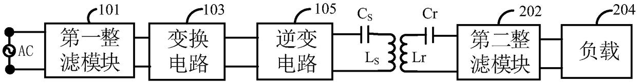
[0036] see figure 1 , an embodiment of the present invention is a wireless charging system for electronic equipment, which includes an energy transmitting end and an energy receiving end, wherein the energy transmitting end and the energy receiving end are connected through an air interface.

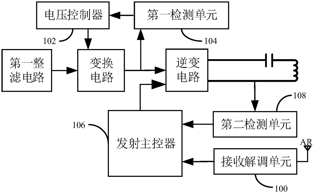
[0037] The energy transmitter includes a first filter module 101 for converting alternating current AC into unidirectional fluctuating direct current, an inverter circuit 105 for converting direct current into high-frequency alternating current wit...


PUM


Abstract

The invention discloses a wireless charging system for an electronic device, aiming to solve the problem of finding an implementation scheme of a wireless charging system with a simple structure. Thesystem comprises an energy transmitting end and an energy receiving end, wherein the energy transmitting end comprises a first integral filtering module, an inverter circuit, a conversion circuit anda transmission resonant network which are connected with each other in order; the energy receiving end comprises a receiving resonant network matched with the transmitting resonant network and a second integral filtering module which are connected with each other in order; the energy transmitting end and the energy receiving end are connected with the receiving resonant network by the transmittingresonant network. The invention realizes the electric energy transmission between the energy transmitting end and the energy receiving end by the setting of the first integral filtering module, the inverter circuit, the converting circuit, the transmitting resonant network, the receiving resonant network matched with the transmitting resonant network and the second integral filtering module, andsimplifies the structure of the wireless charging system at the same time.

Description

technical field [0001] The present invention relates to the field of wireless charging, in particular, the present invention relates to a wireless charging system for electronic equipment. Background technique [0002] As the functions of electronic devices become more and more powerful and the screen size becomes larger and larger, their power consumption also increases, but the development of battery technology has not kept pace with the development of electronic devices. Wired charging is generally an electronic product equipped with a charger. In addition to a large number of chargers and data cables, it will also cause waste of resources. Due to the huge consumption of electronic equipment, the consumption of chargers and data cables is also very large. . In addition, due to the wired charging method itself, a dedicated charging interface must be reserved on the electronic device, which is easily damaged after repeated plugging and unplugging. cause of failure in . ...

Claims


Application Information

Patent Timeline
Patent Type & Authority Applications(China)
IPC IPC(8): H02J50/12H02J50/80
CPCH02J50/12H02J50/80
Inventor 王爱元庄石榴
Owner SHANGHAI DIANJI UNIV
Why Eureka
Try Eureka