Power transmission device for mini-tiller
A technology of power transmission device and micro-cultivator, which is applied in the direction of transmission device control, mechanical control device, tillage equipment, etc., can solve the problems of large resistance between gearbox and ground, low failure rate, etc., achieve long power output, reduce load, Manpower saving effect
- Summary
- Abstract
- Description
- Claims
- Application Information
AI Technical Summary
Problems solved by technology
Method used
Image
Examples
Embodiment 1
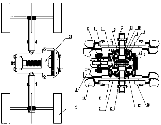
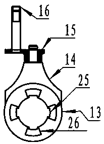
[0039] When rotary tillage and weeding are required, before starting the tiller, the operating lever 16 is moved to the left side of the knife shaft 2, and the shift fork 14 is driven to the knife shaft 2 by the shift fork connecting rod 15 of the clutch, shifting and reversing device. Swipe to the right of the . The shift fork 14 slides to the right side of the cutter shaft 2 to drive the dial sleeve 13 to slide synchronously to the right side of the cutter shaft 2, so that the four trapezoidal convex teeth on the right end surface of the dial sleeve 13 are inserted into the four trapezoidal teeth on the inner end surface of the right spiral bevel gear 9. Trapezoidal concave keyway.
[0040] After starting the machine, the power is input from the longitudinal helical gear shaft 7, and the helical gear shaft 7 is always meshed with the left helical bevel gear 5 and the right helical bevel gear 9 through the helical bevel gear 17, and the left helical bevel gear 5 and the right...
Embodiment 2
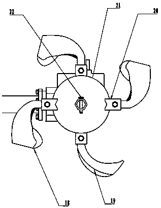
[0042] When ditching is required, before starting the tiller, install the ditching knife group on the knife shaft 2 through the pin shaft 22, move the operating lever 16 to the right side of the knife shaft 2, and drive it through the fork connecting rod 15 Shift fork 14 slides to the left side of cutter shaft 2. The shift fork 14 slides to the left side of the cutter shaft 2 and drives the dial sleeve 13 to slide to the left, so that four trapezoidal protruding teeth on the left end face of the dial sleeve 13 are inserted into four trapezoidal grooves on the inner end face of the left spiral bevel gear 5 .
[0043] After starting the machine, power is input from the vertical helical gear shaft 7, and its one end helical bevel gear 17 is always engaged with the left helical bevel gear 5 and the right helical bevel gear 9, and both rotate simultaneously. The four protruding teeth on the right end surface of the dial sleeve 13 are in a disengaged state from the four grooves on t...
Embodiment 3
[0046] When it is necessary to climb slopes, climb mountains, or move between plots, before starting the tiller, set the operating lever 16 to the middle position, and drive the shift fork connecting rod 15 and the shift fork 14 to slide to the middle position, and the shift fork 14 drives the shifter The sleeve 13 is slid to the middle position. After starting the machine, power is input from the vertical helical gear shaft 7, and the helical bevel gear 17 at one end meshes with the left helical bevel gear 5 and the right helical bevel gear 9, driving both to rotate simultaneously.
[0047] Because shift fork 14 is in the middle position, four protruding teeth of its left and right end surfaces are in disengagement state simultaneously with left helical bevel gear 5 and right helical bevel gear 9, power can't be transmitted to shift fork 13, and cutter shaft 2 also loses power thereupon. Now the road wheel 23 rotates and the cutter shaft 2 does not rotate, so that climbing, m...
PUM
 Abstract
Description
Claims
Application Information
 - R&D
- Intellectual Property
- Life Sciences
- Materials
- Tech Scout
- Unparalleled Data Quality
- Higher Quality Content
- 60% Fewer Hallucinations
Browse by: Latest US Patents, China's latest patents, Technical Efficacy Thesaurus, Application Domain, Technology Topic, Popular Technical Reports.
© 2025 PatSnap. All rights reserved.Legal|Privacy policy|Modern Slavery Act Transparency Statement|Sitemap|About US| Contact US: help@patsnap.com


