
Energy-saving heat tank

A technology of a hot tank and an electric heating tube, which is applied to beverage preparation devices, household appliances, applications, etc., can solve the problems of high shell manufacturing cost, high manufacturing and installation cost, limited use range, etc., achieve compact size, reduce manufacturing and installation cost, Ensure thorough disinfection

Pending Publication Date: 2018-06-29
JIANGSU CIKON ENVIRONMENTAL APPLIANCE CO LTD
View PDF0 Cites 0 Cited by
  • Summary
  • Abstract
  • Description
  • Claims
  • Application Information

AI Technical Summary

Problems solved by technology

Although the system can realize the basic function of providing boiled water and cold boiled water at the same time, the system also has defects: first, the heat tank, heat exchanger and connecting pipelines are exposed to the outside, resulting in a large heat dissipation area and low energy efficiency; second, The heat tank and heat exchanger are set separately and the pipelines connecting each other determine the high cost of manufacturing and installation. At the same time, it also determines that the system requires a certain amount of space to install and install, which is relatively large (referring to the three dimensions of length, width, and height) The space requirements limit the scope of use of the system, and the larger space also means that the casing of the device is larger, which in turn leads to higher manufacturing costs of the casing of the machine

Method used


Image

  • Energy-saving heat tank
  • Energy-saving heat tank
  • Energy-saving heat tank

Examples


Embodiment 1

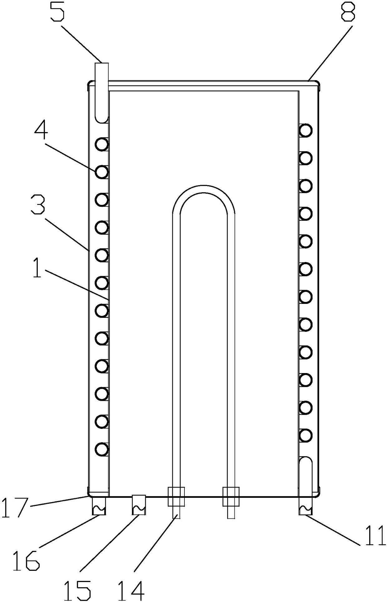
[0042] like figure 2 Shown is a schematic structural diagram of an energy-saving heat tank provided in this embodiment. This energy-saving heat tank includes an inner cylinder 1, an outer cylinder 3, a spiral pipe 4, an upper opening 5, a top plate 8, a lower opening 11, an electric heating pipe 14, a water inlet 15, a water outlet 16 and a bottom plate 17.

[0043] The top end of the outer cylinder 3 is in sealing connection with the top plate 8, and the bottom end of the outer cylinder 3 is in sealing connection with the bottom plate 17; the inner cylinder 1 is arranged in the cavity of the outer cylinder 3, and the straight line where the central axis of the inner cylinder 1 is located radiates outward to any The airspace included in the inner side wall of the cylinder is the inner chamber, the airspace included in the outer cylinder 3 and the outer sidewall of the adjacent cylinder is the outer chamber, the inner space of the inner cylinder 1 is the inner chamber in the p...

Embodiment 2

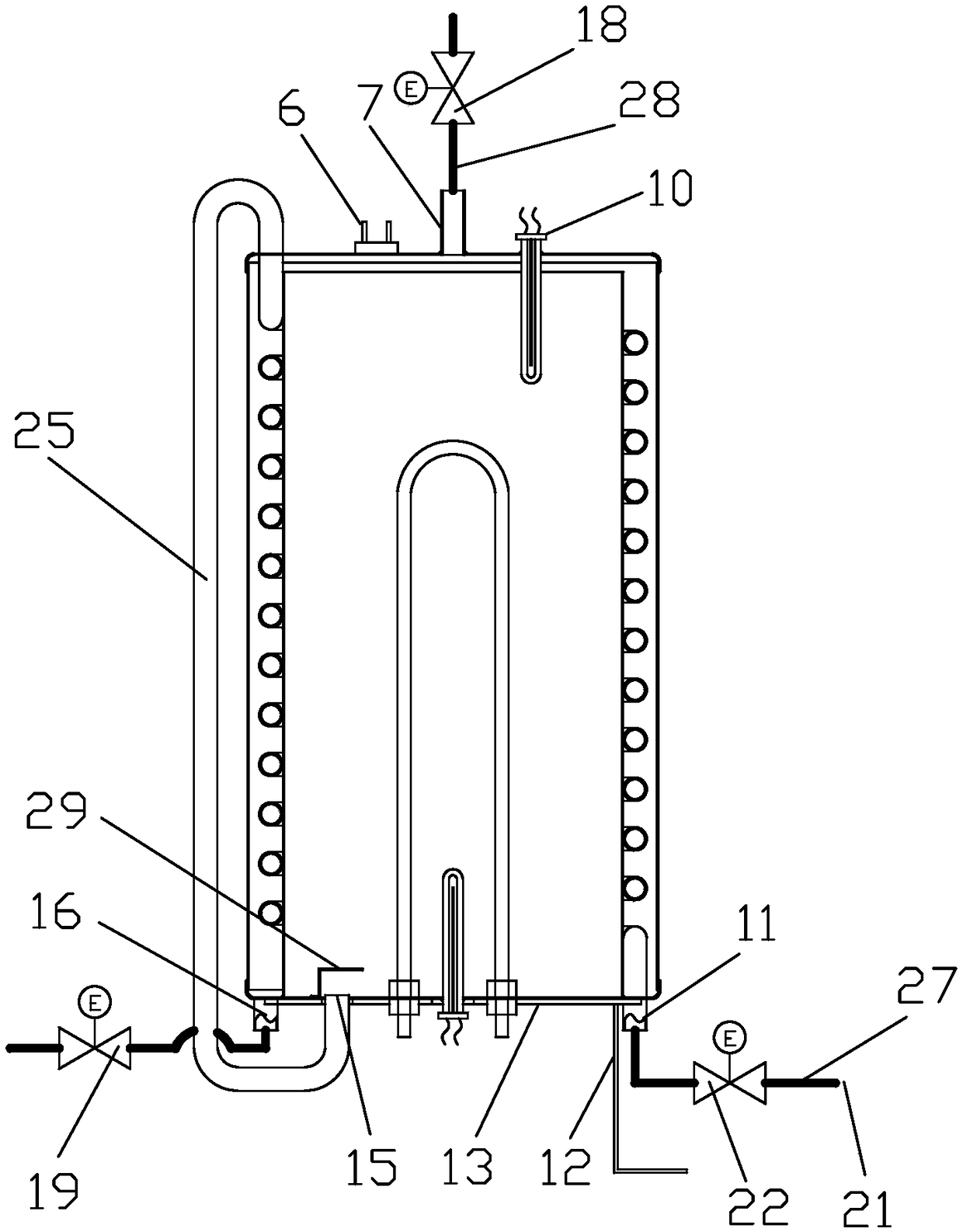
[0046] like image 3 Shown is a schematic structural diagram of the energy-saving heat tank and connecting pipelines provided in this embodiment. The difference between this embodiment and Embodiment 1 is that it also includes a water inlet pipe 27, a water inlet valve 22, a connecting pipe 25, a cold boiled water outlet valve 19, a cold boiled water outlet pipe, a hot water outlet 7, a hot water pipe 28 and a hot water outlet. Water valve 18.

[0047] The top plate 8 is provided with a hot water port 7 connected to the top of the inner cavity; a hot water pipe 28 is connected to the hot water port 7, and a hot water valve 18 is arranged on the hot water pipe 28; Valve 22 is installed on the water inlet pipe 27; One end of connecting pipe 25 is connected with upper opening 5, and the other end is connected with water inlet 15;

[0048] During operation, water enters from the water inlet 21 at normal temperature through the water inlet pipe 27 from the lower opening 11, flows...

Embodiment 3

[0058] like Figure 5 Shown is a schematic structural diagram of the energy-saving heat tank and connecting pipelines provided in this embodiment. The difference between this embodiment and the second embodiment is that: a bypass pipe 26 and a bypass valve 20 are also included. The water source inlet 21 is also connected with a bypass pipe 26, and the other end of the bypass pipe 26 is communicated with the connecting pipe 25, and the bypass valve 20 is installed on the bypass pipe 26. The effect of setting the external pipeline like this is to be able to carry out high-temperature hot water disinfection to the cold boiled water outlet pipeline. The water temperature of the cold boiled water pipeline is usually controlled at about 40°C when the water outlet is normal. Such water temperature is easy to breed bacteria, so it is necessary to regularly sterilize the cold boiled water outlet pipeline.

[0059] The energy-saving heat tank is in a non-sterile state, the bypass valv...


PUM


Abstract

The invention provides an energy-saving heat tank. The energy-saving heat tank comprises an outer cylinder, a top plate, a bottom plate, an electrical heating tube and a helix tube; the top end of theouter cylinder is in sealing connection with the top plate, the bottom end of the outer cylinder is in sealing connection with the bottom plate, the energy-saving heat tank further comprises an innercylinder arranged in a cavity of the outer cylinder, an empty area included in that a straight line where the center axis of the inner cylinder locates extends outward to the inner side wall of any cylinder is an inner cavity, an empty area included in the outer cylinder and the outer side wall of an adjacent cylinder is an outer cavity; a water channel is arranged between the upper end of the inner cylinder and the lower surface of the top plate, the lower end of the inner cylinder is in sealing connection with the bottom plate; the electrical heating tube is fixed on the top plate or the bottom plate, a heating part of the electrical heating tube extends into the inner cavity; the helix tube is arranged in the outer cavity or winds on the outer side wall of the cylinder adjacent to theouter cylinder; an upper opening and lower opening of the helix tube both run through the outer cavity; the bottom plate is provided with a water inlet communicated with the inner cavity, and the outer cylinder or the bottom plate is provided with a water outlet communicated with the outer cavity. Compared with the prior art, the scheme has a significant energy-saving effect and low cost.

Description

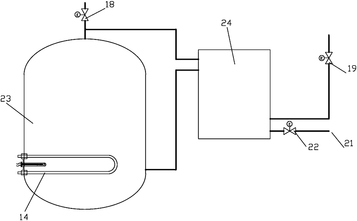
technical field [0001] The invention relates to the field of drinking water equipment, in particular to an energy-saving hot tank for water dispensers. Background technique [0002] Some commercial water dispensers, especially the water dispensers for teachers and students in primary and middle schools, need to provide boiled water to teachers and students, and because the students have a short break between classes, this requires the water dispenser to provide instant drinkable cold boiled water at the same time. This drinking water equipment that can provide drinking water (such as providing boiled water and cold boiled water or only providing cold boiled water, etc.) to many people at the same time is also called a drinking water platform in the industry. At present, the heating system and pipeline design of most drinking water platforms are as follows: figure 1 As shown, the heating system wherein is provided with heat tank 23 and heat exchanger 24 respectively, and hea...

Claims


Application Information

Patent Timeline
Patent Type & Authority Applications(China)
IPC IPC(8): A47J31/54
CPCA47J31/54
Inventor 徐立农黄樟焱
Owner JIANGSU CIKON ENVIRONMENTAL APPLIANCE CO LTD
Learn More