Biological deodorization device and deodorization method thereof

A technology for biological deodorization and deodorization, which is applied in chemical instruments and methods, separation methods, gas treatment, etc., can solve the problem of difficult to achieve uniform spray water distribution, low gas-liquid mass transfer efficiency of pollutants, and liquid film mass transfer. Low efficiency and other problems, to achieve the effects of complete degradation of pollutants, reduction of reaction dead zones, and avoidance of uneven growth of biofilms

Pending Publication Date: 2018-06-29
NISHIHARA ENVIRONMENT ENG SHANGHAI CO LTD
View PDF0 Cites 4 Cited by
  • Summary
  • Abstract
  • Description
  • Claims
  • Application Information

AI Technical Summary

Problems solved by technology

[0006] 3) The gas-liquid mass transfer effect is poor
When the existing biological deodorization device is in operation, the spraying method of the spraying liquid is usually intermittent spraying, the purpose is to keep the filling in the device moist, when the spraying liquid is spraying intermittently, the pollutants can only be discharged most of the time. Through the static liquid film on the surface of the filler into the microbial body, the mass transfer efficiency of the liquid film of the pollutants is lower than that of the spray liquid, and the treatment efficiency will be reduced.
Similarly, when the cross-sectional area of ​​the device is too large, it is also difficult to realize the uniformity of spray water distribution.
[0007] In summary, due to the shortcomings of the existing biological deodorization devices, such as uneven gas distribution, large differences in pollutant removal load along the packing layer, and low efficiency of gas-liquid mass transfer of pollutants, the effective volume of the device is reduced and the processing load is reduced. Low, the treatment effect is not good, it is difficult to meet the increasingly high deodorization requirements of today

Method used


Image

  • Biological deodorization device and deodorization method thereof
  • Biological deodorization device and deodorization method thereof

Examples


Embodiment Construction

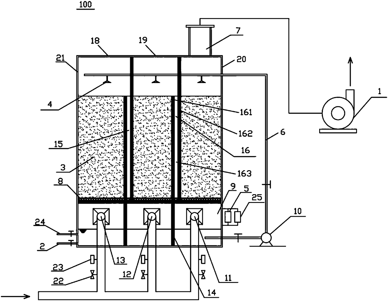
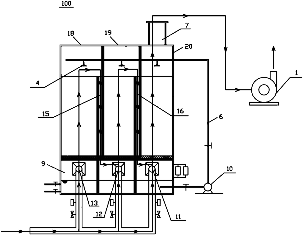
[0027] Embodiments of the technical solutions of the present invention will be described in detail below in conjunction with the accompanying drawings. The following examples are only used to illustrate the technical solutions of the present invention more clearly, and therefore are only examples, rather than limiting the protection scope of the present invention.

[0028] The present invention proposes a biological deodorization device 100, the biological deodorization device 100 includes: a housing 21, the housing 21 includes a plurality of deodorizing sections formed at intervals in sequence and connected between adjacent deodorizing sections The top of the casing 21 is provided with an exhaust port 7 communicating with the outlet of the last deodorizing section, and each deodorizing section includes an air inlet formed at the bottom of the casing 21. Wherein, the inlet of each transition section communicates with the outlet of the deodorizing section in front of it, and th...


PUM


Abstract

The invention belongs to the field of biological deodorization, and discloses a biological deodorization device and a deodorization method thereof. The biological deodorization device comprises a shell, wherein the shell comprises a plurality of deodorization sections which are formed according to horizontal intervals in sequence, and each transition section arranged between adjacent deodorizationsections; the top of the shell is provided with an exhaust port communicated with the outlet of the last deodorization section; each deodorization section respectively comprises an air inlet formed on the bottom of the shell; the inlet of each transition section is communicated with the outlet of the deodorization section in front of the transition section; in addition, the outlet of each transition section is communicated with the air inlet of the deodorization section behind the transition section to enable bad smell entering from the air inlet of one deodorization section to be mixed withbad smell entering from the air inlet of the adjacent deodorization section after passing through the deodorization section and the transition section behind the deodorization section to enter the adjacent deodorization section, and finally, the mixed gas is discharged out of the shell through the exhaust port. The biological deodorization device disclosed by the invention has the advantages of higher processing load and better deodorization effect.

Description

technical field [0001] The invention relates to the field of biological deodorization, in particular to a biological deodorization device and a deodorization method using the same. Background technique [0002] With the rapid progress of urbanization in my country, sewage treatment plants are gradually surrounded by urban expansion, and the odorous gases produced by them (such as hydrogen sulfide, ammonia, methyl mercaptan, methyl sulfide, dimethylamine and volatile organic compounds, etc. Gases of polluting substances) will seriously affect the surrounding environment and the health of residents, resulting in a serious "NIMBY" effect. Obviously, how to purify the odor of urban sewage treatment plants is imminent. [0003] At present, the methods for treating the odor generated by sewage treatment plants in this field mainly include biological methods, activated carbon adsorption methods, chemical washing methods, plasma methods, and the like. Among them, the biological met...

Claims


Application Information

Patent Timeline
Patent Type & Authority Applications(China)
IPC IPC(8): B01D53/84
CPCB01D53/84B01D2251/95B01D2257/304B01D2257/306B01D2257/406B01D2257/70B01D2257/708Y02A50/20
Inventor 曹效鑫周晓长英夫刘启凯鞠庆玲席劲瑛庞洪涛
Owner NISHIHARA ENVIRONMENT ENG SHANGHAI CO LTD
Why Eureka
Try Eureka