
Nozzle forging method and nuclear power main pump casing copy forging process

A technology for nozzles and cylinders, which is applied in the field of nozzle forging methods and nuclear power main pump casing profiling forging technology, can solve the problems of low material utilization rate of forgings, low material utilization rate, and large forging weight, and achieve the reduction of material Cost, forging weight reduction, and manufacturing cost reduction effect

Active Publication Date: 2019-07-16
CHINA ERZHONG GRP DEYANG HEAVY IND
View PDF5 Cites 0 Cited by
  • Summary
  • Abstract
  • Description
  • Claims
  • Application Information

AI Technical Summary

Problems solved by technology

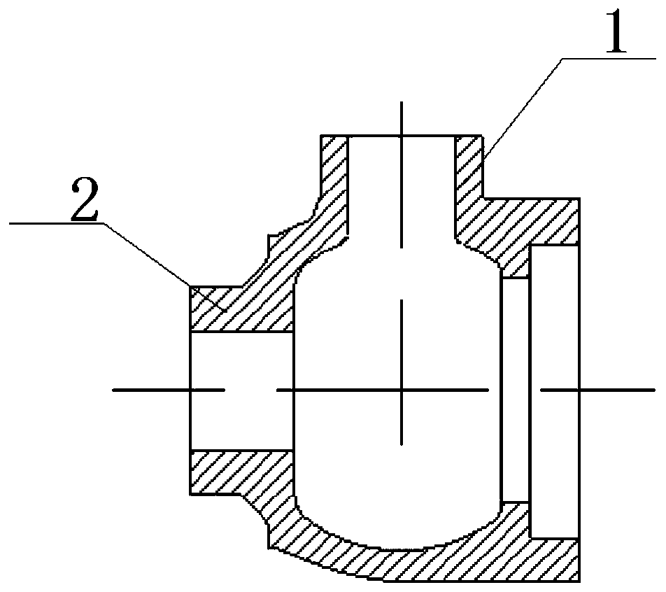
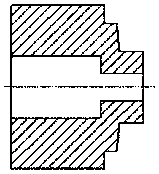
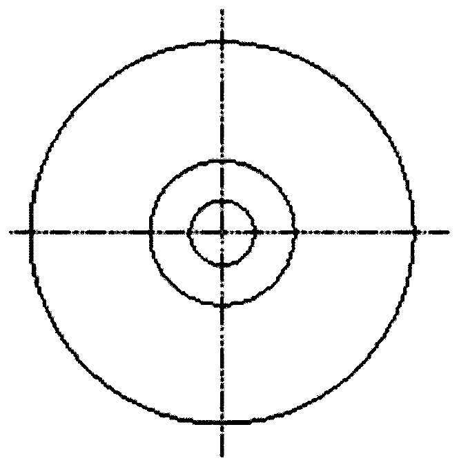
[0005] ① Free forging to form hollow forgings, see forging structure diagram figure 2 and image 3 , the forging nozzle adopts solid envelope forming, the forging weight is large, and the material utilization rate is low
[0006] ②Tire die forging to form a solid forging, see the forging structure diagram Figure 4 and Figure 5 , the nozzle is forged in a solid envelope method, the forging is a solid structure, the forging is heavy, and the material utilization rate is low
[0007] ③Extrusion forming, forging structure see Image 6 , use the punch to extrude the billet to form 2 nozzles, all of which are solid structures, and the material utilization rate is low
[0008] Therefore, based on the shortcomings of the low utilization rate of forging materials, a copy forging method with high material utilization rate was invented. This method uses a special forming device to forge all the two nozzles

Method used


Image

  • Nozzle forging method and nuclear power main pump casing copy forging process
  • Nozzle forging method and nuclear power main pump casing copy forging process
  • Nozzle forging method and nuclear power main pump casing copy forging process

Examples


Embodiment Construction

[0042] The present invention will be further described by taking the profiling forging of the pump casing forging of the nuclear power main pump as an example below.

[0043] The main steps of the profiling forging process for pump casing forgings of nuclear power main pumps are as follows:

[0044] ①Steel ingot pressing jaw, after the steel ingot is heated, the riser presses the jaw, which is convenient for the clamping operation of the next upsetting process;

[0045] ②Upsetting and blanking, upsetting and drawing the billet to lengthen the billet to improve the structural defects of the steel ingot;

[0046] ③ Upsetting and punching, after blanking, upsetting and punching the billet to make a billet for hole expansion;

[0047] ④ The horse bar is reamed, the horse bar is reamed until the diameter meets the size of the intermediate blank, and the intermediate blank is made, and the intermediate blank is the cylinder blank 9;

[0048] ⑤ Process a positioning hole on the cyl...


PUM


Abstract

The invention relates to the field of forging, and discloses a tube nozzle forging method and a nuclear main pump shell profiled forging process. The tube nozzle forging method comprises the followingsteps: forging of a first tube nozzle: processing a positioning hole in a barrel blank; locally heating the positioning hole; placing the barrel blank on a lower die, arranging a guide column which is matched with the positioning hole in a flute of the lower die, and enabling the guide column to penetrate through the positioning hole to position the barrel blank; carrying out pre-punching in thebarrel blank by using a first punch, forming a first guide hole which corresponds to the guide column in the first punch, inserting the guide column into the first guide hole to form a cavity in the barrel blank, and carrying out impact extrusion in the barrel blank by using the first punch, wherein the diameter of the second punch is smaller than that of the first punch; and forming a second guide hole which corresponds to the guide column in the second punch, and inserting the guide column into the second guide hole during impact extrusion to form a first tube nozzle. The utilization rate ofmaterials can be increased, the machining amount is reduced, the deformation degree of forge pieces is large, the quality of the forge pieces is good, and the performance is excellent.

Description

technical field [0001] The invention relates to the field of forging, in particular to a nozzle forging method and a nuclear power main pump shell profiling forging process. Background technique [0002] The main pump is the only active equipment within the reactor pressure boundary and is the key main equipment of the passive reactor. The pump casing of the main pump is the core pressure-bearing part of the main pump, a nuclear safety first-class equipment, and belongs to the core equipment of the nuclear island of the nuclear power plant. It is required to be manufactured in accordance with the world's highest nuclear power safety requirements and the most stringent technical standards. [0003] In the past, complex products such as pump casings were manufactured by casting, but in recent years, with the improvement of third-generation nuclear power technology requirements, in order to further improve its safety and service life in nuclear power plants, the performance of...

Claims


Application Information

Patent Timeline
Patent Type & Authority Patents(China)
IPC IPC(8): B21J1/04B21J5/08B21J5/10B21J5/02
CPCB21J1/04B21J5/002B21J5/025B21J5/08B21J5/10
Inventor 刘金豪孙嫘毛闯沈国劬蒋新亮
Owner CHINA ERZHONG GRP DEYANG HEAVY IND
Learn More