Brazing system carrying out heating/cooling by using gas as medium
A medium and gas technology, applied in the direction of metal processing, welding equipment, metal processing equipment, etc., can solve the problems of uneven heating on the surface of the workpiece, inaccurate data measurement, and improve working time, so as to shorten the heating or cooling time, heat or Uniform cooling and high energy utilization
- Summary
- Abstract
- Description
- Claims
- Application Information
AI Technical Summary
Problems solved by technology
Method used
Image
Examples
Embodiment 1
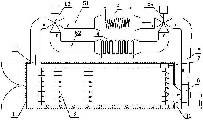
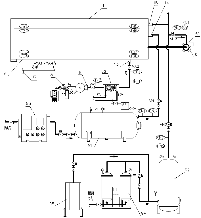
[0042] Such as figure 1 with figure 2 Shown: a brazing system using gas as a medium for heating / cooling, including a furnace body 1, a vacuum system 8 and a gas supply system 9. A workpiece 2 is arranged in the furnace cavity of the furnace body 1, and the furnace body 1 is provided with an air inlet 11 and an air outlet 12, and the outside of the furnace body 1 is provided with a circulation pipe 5, and is connected to the air inlet 11 and the outlet of the furnace body 1. Between the gas ports 12; a heater 3 and a cooler 4 are provided on the circulation pipe 5, and the hot gas or cold gas is introduced into the inner cavity of the workpiece 2 through the circulation pipe 5 through the induced draft fan 6, and the workpiece 2 is cyclically heated or cooled; The body 1 is also provided with a vacuum port 13 and a protective gas input port; the vacuum pumping system 8 is connected to the vacuum port 13 for keeping the workpiece in a non-oxygen environment. The gas supply sy...
Embodiment 2
[0061] The difference with Embodiment 1 is that the heater and the cooler are connected to two branches of a circulation pipeline, that is, the heater branch and the cooler branch, and a first electric valve is provided at the inlet of the heater, and the cooler A second electric valve is provided at the entrance, and the valve openings of the two electric valves can be adjusted. When the first electric valve is controlled to open, the circulation pipeline forms a hot air passage; when the second electric valve is controlled to open, the circulation pipe forms a cold air passage.
[0062] Of course, the first electric valve and the second electric valve can also be replaced by manual valves.
[0063] Other structures are with embodiment 1.
Embodiment 3
[0065] The difference from Embodiment 1 is that the heater and the cooler are respectively connected to a circulation pipeline, i.e. a heater pipeline and a cooler pipeline, the heater pipeline is arranged on the upper side of the furnace body, and the cooler pipeline is arranged on the lower side of the furnace body, The two pipelines work independently and do not affect each other. The two pipelines are respectively connected to the inlet and outlet of the furnace body. The heater pipeline and the cooler pipeline are respectively connected to the induced draft fan to transport the gas into the pipeline.
[0066] A third electric valve is arranged at the inlet of the heater, and a fourth electric valve is arranged at the inlet of the cooler.
[0067] The settings of the insulation sleeve, the pressure gauge and the vacuum valve are the same as in Embodiment 2.
[0068] Other structures are with embodiment 1.
PUM
 Abstract
Description
Claims
Application Information
 - R&D
- Intellectual Property
- Life Sciences
- Materials
- Tech Scout
- Unparalleled Data Quality
- Higher Quality Content
- 60% Fewer Hallucinations
Browse by: Latest US Patents, China's latest patents, Technical Efficacy Thesaurus, Application Domain, Technology Topic, Popular Technical Reports.
© 2025 PatSnap. All rights reserved.Legal|Privacy policy|Modern Slavery Act Transparency Statement|Sitemap|About US| Contact US: help@patsnap.com


