
Cutter head grinding device

A grinding and cutter head technology, which is applied in the direction of grinding drive device, grinding/polishing safety device, grinding frame, etc., can solve the problem of long wire cutting time, low cutting precision, low cutting efficiency and low cutting speed. Problems such as low machining accuracy

Pending Publication Date: 2018-06-29
HUNAN ZDCY (ZHONGDA CHUANG YUAN) CNC EQUIP CO LTD
View PDF0 Cites 5 Cited by
  • Summary
  • Abstract
  • Description
  • Claims
  • Application Information

AI Technical Summary

Problems solved by technology

[0003] However, the cutting time of slow wire cutting is long, and the cutting accuracy is not high, which leads to the low processing efficiency and processing accuracy of the cutter head.

Method used


Image

  • Cutter head grinding device
  • Cutter head grinding device
  • Cutter head grinding device

Examples


Embodiment Construction

[0040] The core of the present invention is to provide a cutterhead grinding device to improve the machining efficiency and precision of the cutterhead.

[0041] The following will clearly and completely describe the technical solutions in the embodiments of the present invention with reference to the accompanying drawings in the embodiments of the present invention. Obviously, the described embodiments are only some, not all, embodiments of the present invention. Based on the embodiments of the present invention, all other embodiments obtained by persons of ordinary skill in the art without making creative efforts belong to the protection scope of the present invention.

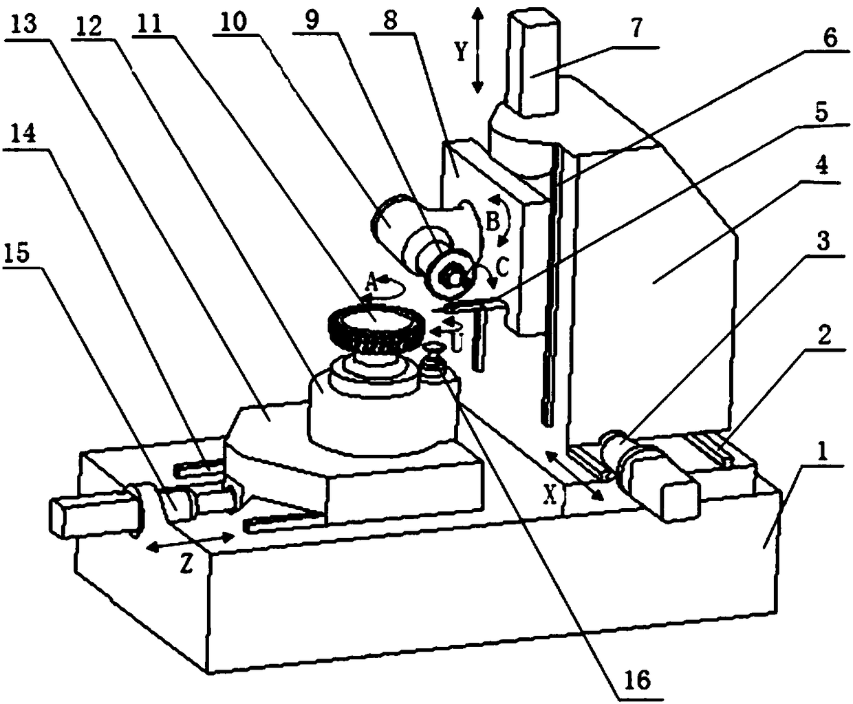
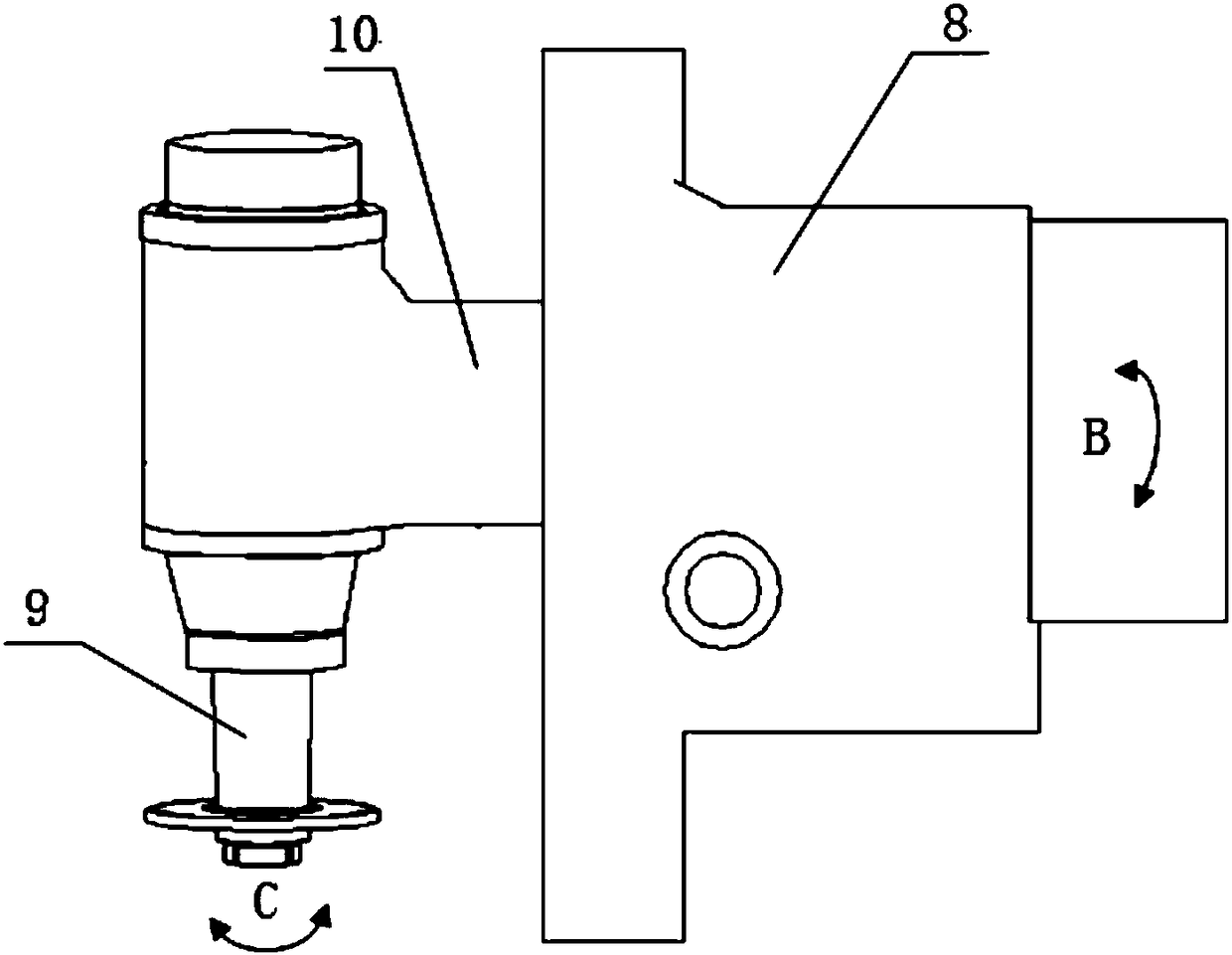
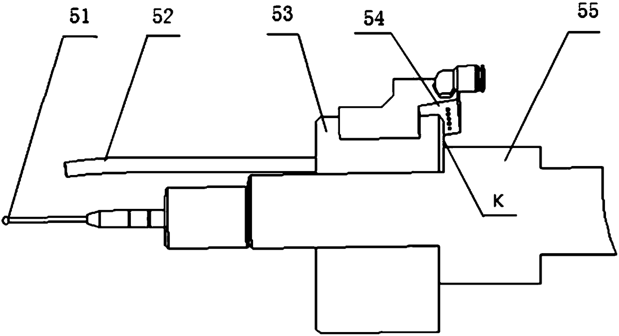
[0042] Such as figure 1 with figure 2 As shown, a cutterhead grinding device provided by the embodiment of the present invention includes: a bed 1, a workpiece box 12, a column 4, a B-axis box 8, a grinding wheel box 10 and a relative motion driving mechanism. Wherein, the workpiece box 12 , the column 4 ...


PUM


Abstract

The invention discloses a cutter head grinding device. The cutter head grinding device comprises a lathe bed, a workpiece box body, a stand column, a B-axis box body, a grinding wheel box body and a relative motion driving mechanism. The workpiece box body is arranged on the lathe bed and internally provided with a workpiece rotating shaft, wherein the workpiece rotating shaft is used for allowinga workpiece to be fixedly mounted thereon, and the workpiece rotating shaft is rotatably arranged in the workpiece box body. The stand column is arranged on the lathe bed. The B-axis box body is arranged on the stand column and internally provided with a grinding wheel box body swinging shaft, wherein the grinding wheel box body swinging shaft is used for allowing the grinding wheel box body to be fixedly mounted thereon, and the grinding wheel box body swinging shaft is rotatably arranged in the B-axis box body. The grinding wheel box body is arranged on the B-axis box body and provided witha grinding wheel rotating shaft, wherein the grinding wheel rotating shaft is used for allowing a grinding wheel to be fixedly mounted thereon; the grinding wheel rotating shaft is rotatably arrangedin the grinding wheel box body; and the grinding wheel box body can rotate relative to the stand column, and the rotation axis direction is perpendicular to the grinding wheel rotating shaft. The relative motion driving mechanism is arranged on the lathe bed and used for driving the workpiece box body to move relative to the stand column. By means of the cutter head grinding device, machining efficiency and machining precision are improved.

Description

technical field [0001] The invention relates to the technical field of machine tools, in particular to a cutter head grinding device. Background technique [0002] At present, the processing of the cutter head generally adopts the method of slow wire cutting. Slow wire cutting is a kind of wire electric discharge cutting. By using a continuously moving thin metal wire (called an electrode wire) as an electrode, the workpiece is subjected to pulse spark discharge to etch the metal and cut into shape, and then processed into a cutter head. [0003] However, the cutting time of slow wire cutting is long, and the cutting precision is not high, which leads to low processing efficiency and processing precision of the cutter head. [0004] Therefore, how to improve the machining efficiency and machining accuracy of the cutter head has become a technical problem to be solved urgently by those skilled in the art. Contents of the invention [0005] The object of the present inven...

Claims


Application Information

Patent Timeline
Patent Type & Authority Applications(China)
IPC IPC(8): B24B3/46B24B41/02B24B41/06B24B47/20B24B49/00B24B55/06
CPCB24B3/46B24B41/02B24B41/061B24B47/20B24B49/00B24B55/06
Inventor 李桂文李锡晗丁志文尚吉顺陈静宇肖为
Owner HUNAN ZDCY (ZHONGDA CHUANG YUAN) CNC EQUIP CO LTD
Learn More