
Driving device for linear movement, pickup device unit and transfer operation equipment

A driving device, linear motion technology, applied in the direction of transmission, mechanical equipment, transportation and packaging, etc., can solve problems such as expansion of backlash, reduction of service life, noise, etc.

Active Publication Date: 2018-06-29
HON PRECISION INC
View PDF7 Cites 0 Cited by
  • Summary
  • Abstract
  • Description
  • Claims
  • Application Information

AI Technical Summary

Problems solved by technology

[0004] 1. The pulley set is composed of a driving pulley, a driven pulley and a ring-shaped flexible transmission belt. As far as the configuration cost of the components is concerned, the two pulleys plus the ring-shaped flexible transmission belt will cause the use of Configuration cost of more components
[0005] 2. In addition to the definite movement of the ring-shaped flexible transmission belt in contact with the driving pulley and the driven pulley, the other parts of the belt on both sides are flexible and have no flat surface for abutment, so in the transmission Positioning is less reliable
[0007] 1. Since the rack and pinion are made of hard materials, it is easy to generate noise due to collision during meshing transmission
[0008] 2. In addition to the high precision requirements for the meshing of the rack and pinion itself, the overall accumulated assembly error also has high precision requirements, so it requires high production costs
[0009] 3. There must be a small amount of backlash in the meshing of the rack and pinion to make the meshing transmission smoother. However, in terms of long-term use, the collision between the two hard materials will easily cause wear and the backlash will continue to expand. In addition to affecting the positioning Accuracy, and will soon exceed the allowable error value range, and reduce the service life

Method used


Image

  • Driving device for linear movement, pickup device unit and transfer operation equipment
  • Driving device for linear movement, pickup device unit and transfer operation equipment
  • Driving device for linear movement, pickup device unit and transfer operation equipment

Examples


Embodiment Construction

[0056] In order to make your review committee members have a further understanding of the present invention, the preferred embodiments are hereby given in conjunction with the drawings, and are described in detail as follows:

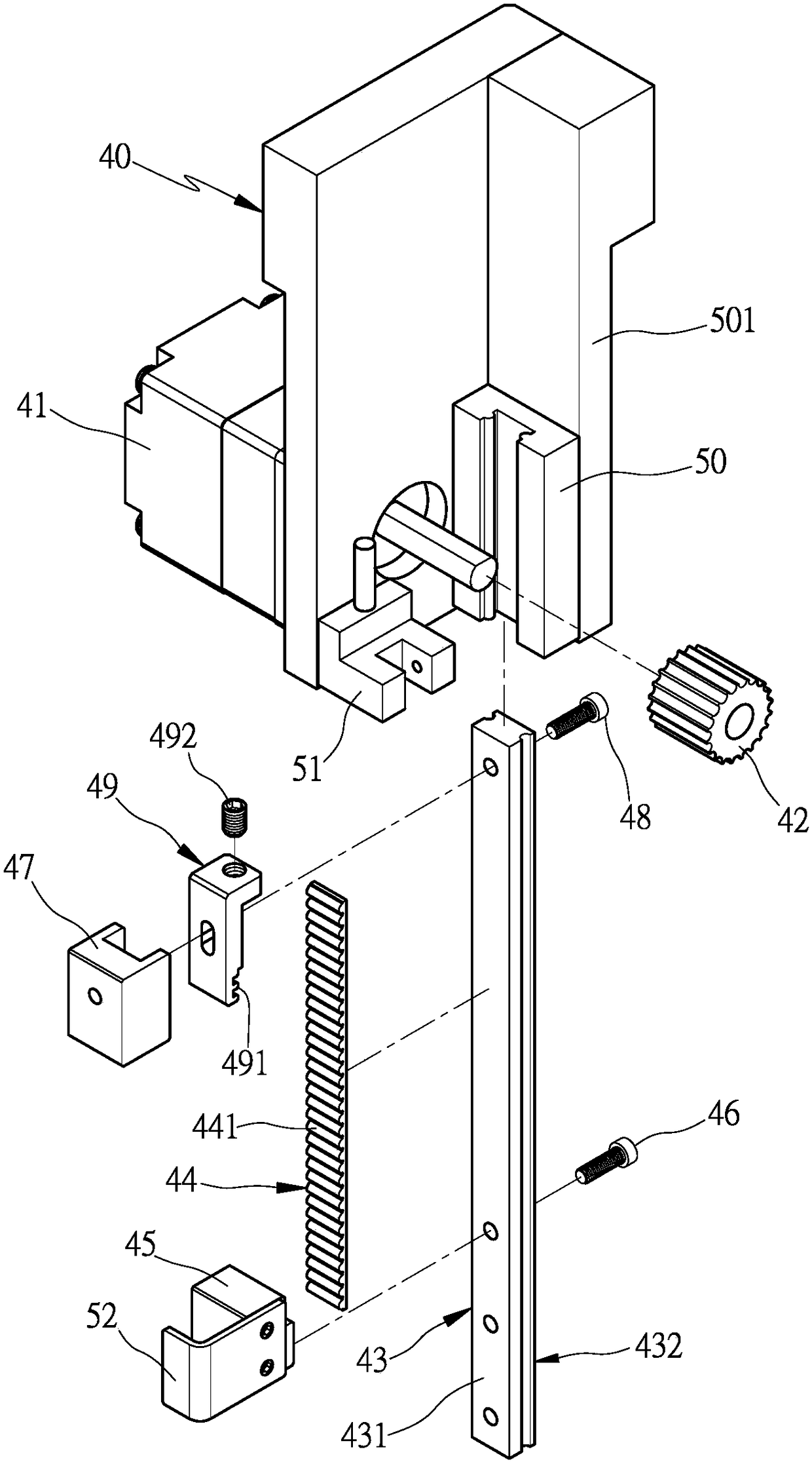
[0057] see image 3 , Figure 4 , Figure 5 The driving device for linear motion of the present invention is to mount a driving source 41 on a base 40, and the driving source 41 is connected with a transmission gear 42, so that the driving source 41 can drive the transmission gear 42 to rotate when actuated. In this embodiment, the driving source 41 is a servo motor, and a transmission gear 42 is connected to the output shaft end; a pair of placement parts 43 is provided with a first surface side 431 at a tooth surface position relative to the transmission gear 42, On the other side opposite to the first surface side 431, a second surface side 432 is provided, and the opposing member 43 is provided with a strip-shaped linear toothed belt 44 meshing wi...


PUM


Abstract

The invention provides a driving device for linear movement, a pickup device unit and transfer operation equipment. The driving device is equipped with a driving source, an oppositely-arranged part. The driving source is connected and equipped with a driving gear. The oppositely-arranged part has a first surface side and a second surface side. The first surface side of the oppositely-arranged partis provided with a linear toothed belt. The circumferential side of the oppositely-arranged part is abutted against a abutting part and enables the driving gear to be engaged with the linear toothedbelt on the first surface side of the oppositely-arranged part and can drive the driving gear during rotation to perform linear movement. Accordingly, reliability of linear movement is ensured and configuration cost is effectively reduced while driving noises are eliminated by utilizing engaged driving of the driving gear and the linear toothed belt. Additionally, precision requirement and accumulative assembly errors required by engaged transmission are effectively compensated. Therefore, benefits such as effective reduction in manufacture cost and longer service lifetime are acquired.

Description

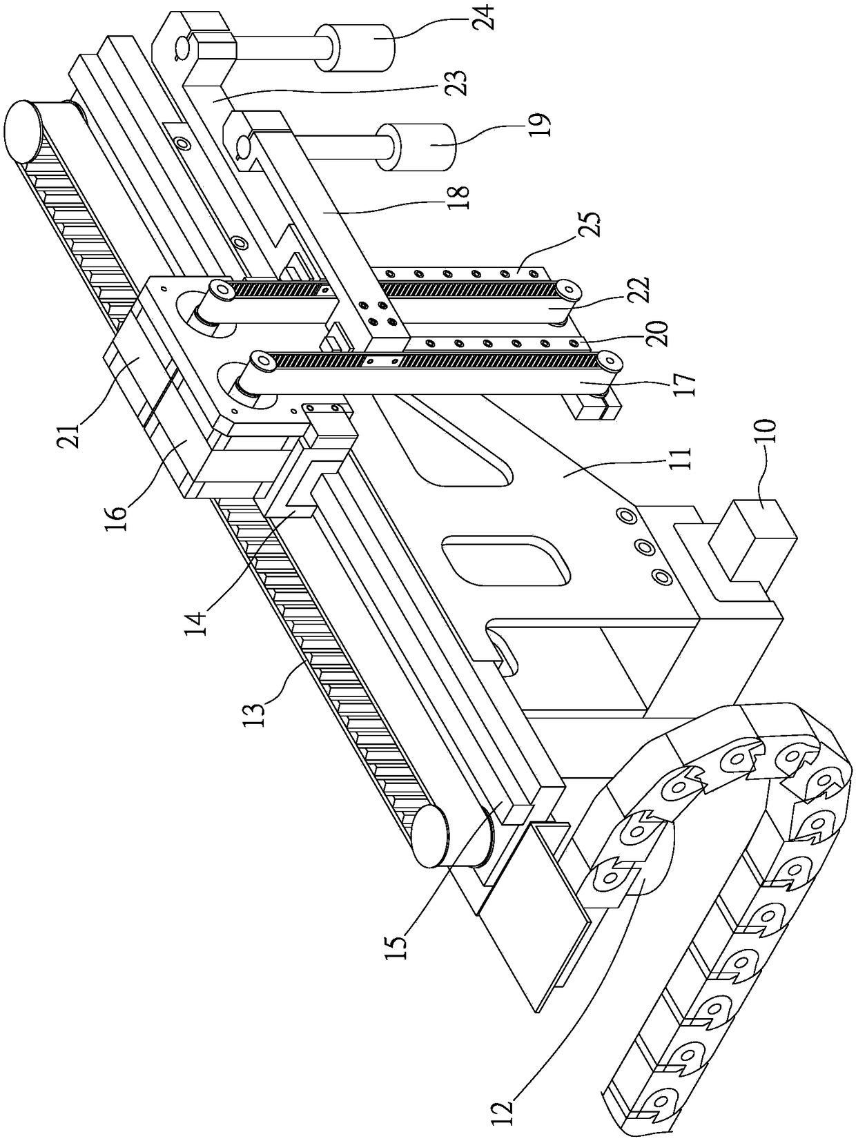
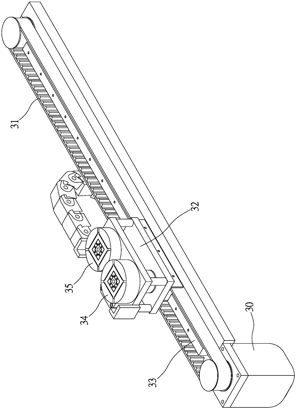
technical field [0001] The invention relates to a device that not only can effectively reduce configuration costs and eliminate transmission noise while ensuring the reliability of linear motion, but also can effectively compensate the precision requirements required for meshing transmission and accumulated assembly errors, so as to effectively reduce production costs and improve use. Life-long linear motion drive device and its applied pick-and-place unit, transfer operation equipment. Background technique [0002] Press, linear motion is a very basic movement mode of automated operation equipment; see figure 1 As shown, taking the pick-and-place unit of the electronic component testing and sorting machine as an example, the pick-and-place unit has a moving arm 11 that can move linearly in the first horizontal direction (X-axis) along the first slide rail 10, the A first drive belt 13 that can be driven by the first motor 12 is installed above the moving arm 11, and a firs...

Claims


Application Information

Patent Timeline
IPC IPC(8): B25J9/02B25J15/06
CPCB25J9/023B25J15/0616F16H7/02B65G43/08B65G47/912B65G49/061B65G2249/04B65G2201/022
Inventor 蔡志欣
Owner HON PRECISION INC
Learn More