Eureka AIR delivers breakthrough ideas for toughest innovation challenges, trusted by R&D personnel around the world.

Plate material cutting device

A cutting device and plate technology, applied in electrostatic, metal processing, electrical components, etc., can solve the problems of uneven stacking of plates, failure to cut the cutting surface, and poor static removal effect, saving space and reducing defective products. efficiency, avoid the effect of plate cutting failure

Pending Publication Date: 2018-06-29
郑州华美彩印纸品有限公司
View PDF5 Cites 0 Cited by
  • Summary
  • Abstract
  • Description
  • Claims
  • Application Information

AI Technical Summary

Problems solved by technology

In this utility model, the vertical lifting of the cutting knife and the friction of the bottom knife cut the plate material alternately. After a period of use, when the end faces of the bottom knife and the cutting knife are no longer flush, the cutting failure of the entire cutting surface will occur, and The electrostatic bar is not in contact with the plates, and the effect of removing static electricity is not good, so the plates after cutting are not stacked neatly

Method used


Image

  • Plate material cutting device
  • Plate material cutting device
  • Plate material cutting device

Examples


Embodiment 1

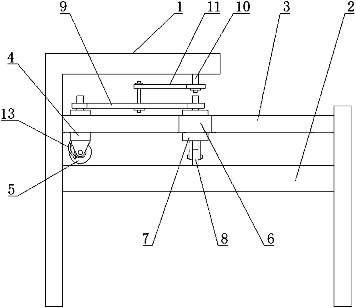
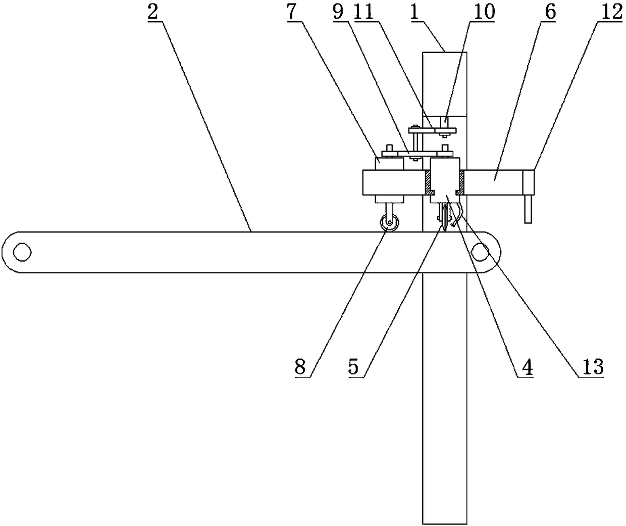
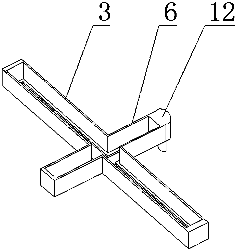
[0032] A plate material cutting device, comprising a bracket 1, an intermittent conveyor belt 2 is arranged on the bracket 1, a guide rail 3 is arranged on the bracket 1, a slider 4 is arranged inside the guide rail 3, and the slider 4 can move along the direction of the guide rail 3 in the guide rail 3 The axis reciprocates, the bottom of the slider 4 is provided with a cutter 5, the support 1 is also provided with a second guide rail 6 perpendicular to the guide rail 3, and the second guide rail 6 is provided with a second slide block 7, the second slide block 7 can be The second guide rail 6 reciprocates along the axis of the second guide rail 6 , and the bottom of the second slider 7 is provided with a metal roller 8 , which is connected with the plate.

[0033]In this embodiment, the cutting knife 5 does not move up and down periodically, but does a reciprocating linear motion in the direction perpendicular to the conveying line of the gap conveyor belt 2. The movement of ...

Embodiment 2

[0035] On the basis of Embodiment 1, in order to save space and reduce volume, the axis of the guide rail 3 and the axis of the second guide rail 7 are in the same plane, and the guide rail 3 and the second guide rail 7 together form a cross guide rail, which is convenient for the slider 4 and the second guide rail. Two slide blocks 7 linkage.

Embodiment 3

[0037] On the basis of Embodiment 1, it also includes a connecting rod 9, one end of the connecting rod 9 is hinged with the slider 4, and the other end of the connecting rod 9 is hinged with the second slider 7; The hinged shaft 10 is sleeved with a crank 11 , and the end of the crank 11 is hinged to the middle part of the connecting rod 9 .

[0038] In this embodiment, it is set so that an ellipse structure is formed between the slider 4 and the second slider 7, so that the slider 4 and the second slider 6 are linked in the cross guide rail, which simplifies the power mechanism required by the device , so that the mechanism of the device is simpler, the actions are more coordinated, and the degree of integration is high, and there is no need to set up a separate control structure to control the movement of the slider 4 and the second slider 7 respectively.


PUM


Abstract

The invention discloses a plate material cutting device, which belongs to the field of box printing and packaging. The plate material cutting device comprises a support, wherein an intermittent conveyor belt is arranged on the support; a guide rail is arranged on the support; a sliding block is arranged in the guide rail and can move in the guide rail along an axis of the guide rail in a reciprocating way; a cutter is arranged on the bottom part of the sliding block; the support is further provided with a second guide rail perpendicular to the guide rail; a second sliding block is arranged onthe second guide rail and can move in the second guide rail along an axis of the second guide rail in a reciprocating way; and a metal roller is arranged on the bottom part of the second sliding blockand is connected with a plate material. According to the plate material cutting device provided by the invention, the cutter is used for intermittently left-and-right reciprocating cutting the platematerial, and an electrostatic wheel linked with the cutter rolls on the plate material so as to adsorb static electricity, so that a cutting section is smooth, and meanwhile, the stacked plate materials after cutting are in order.

Description

technical field [0001] The invention belongs to the field of carton printing and packaging, and in particular relates to a plate material cutting device. Background technique [0002] In the production of carton printing, the plates need to be cut into various specifications according to the usage requirements. In the traditional plate cutting, the cutting tools are manually used in the early stage. The cutting quality is not easy to control, and there are human errors. Mechanized cutting is used in the later stage, but there will always be a lot of powder flocs during the cutting process, the cut section is not smooth, and the knife is prone to generate static electricity during the cutting process, which makes the plates stacked unevenly after cutting. [0003] The Chinese utility model with the notification number CN203236509U discloses a dust collection and static removal plate cutting device, including a floor stand, a knife fixing clip is arranged on the floor stand, a...

Claims


Application Information

Patent Timeline
Patent Type & Authority Applications(China)
IPC IPC(8): B26D1/157B26D5/20B26D7/18B26D7/00H05F3/02
CPCH05F3/02B26D1/1575B26D5/20B26D7/00B26D7/1863B26D2007/0012Y02E60/10
Inventor 崔晓明
Owner 郑州华美彩印纸品有限公司
Why Eureka
Eureka Blog
Learn More