
Environmental sanitation garbage compression device

A technology of garbage compression and sanitation, which is applied in the direction of garbage conveying, garbage collection, storage devices, etc., can solve the problems of difficult to meet processing requirements, high use cost, and difficult operation, and achieves improved compression efficiency, convenient operation, and convenient movement. and transport effects

Inactive Publication Date: 2018-06-29
郑姗姗
View PDF0 Cites 1 Cited by
  • Summary
  • Abstract
  • Description
  • Claims
  • Application Information

AI Technical Summary

Problems solved by technology

[0002] With the continuous enhancement of people's awareness of environmental protection, household garbage has been sorted and stored for secondary recycling and processing. In some large garbage recycling stations, some highly plastic household garbage such as (pop cans, plastic bottles, etc.) need to be cleaned before processing It performs compression treatment to reduce the volume. In the traditional technology, the compression treatment of garbage is generally through manual extrusion. The operation is difficult and inefficient, and it is difficult to meet the processing needs. There are also many automatic sanitation garbage compression devices in the existing , but its structure is complex, the cost of use is high, there are major disadvantages, and it needs to be improved

Method used


Image

  • Environmental sanitation garbage compression device
  • Environmental sanitation garbage compression device
  • Environmental sanitation garbage compression device

Examples


Embodiment Construction

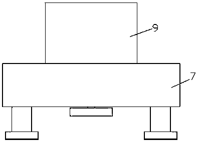
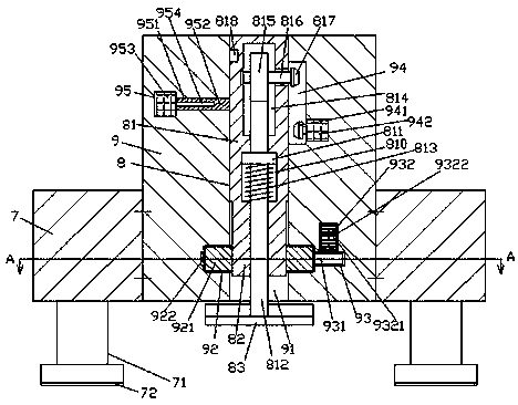
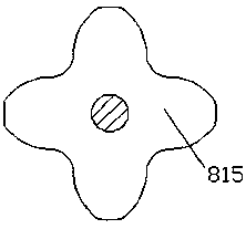
[0020] Such as Figure 1-Figure 5 As shown, a sanitation garbage compression device of the present invention includes a base body 7 and a compressor 9 fixedly installed in the base body 7, and a square sliding groove 91 is provided up and down in the compressor 9 , the lower side wall of the sliding groove 91 is communicated with a first cavity 92, and the first cavity 92 is rotated and connected with a disc 921. The right side of the first cavity 92 The compressor 9 is provided with a first transfer chamber 93, and a toothed wheel 931 is connected to the rotation in the first transfer chamber 93, and the top of the toothed wheel 931 is connected to the first motor 932, and the first The outer surface of the motor 932 is set in the inner wall of the top of the first transfer chamber 93 and is fixedly connected, and the outer surface of the disc 921 is fixedly provided with a toothed ring 922, and the right side of the toothed ring 922 penetrates into the Inside the first tran...


PUM


Abstract

The invention discloses an environmental sanitation garbage compression device comprising a seat body and a compressor fixedly installed in the seat body. The compressor is internally provided with asquare sliding transport slot in a vertically through manner, the lower side wall of the sliding transport slot is internally provided with a first cavity portion in a communicating and surrounding manner, and the first cavity portion is internally connected with a circular disc in a rotary fit manner. The portion, on the right side of the first cavity, of the compressor is internally provided with a first transfer cavity, the first transfer cavity is internally connected with a tooth-shaped wheel in a rotary fit manner, and the top of the tooth-shaped wheel is connected with a first motor ina matched manner. The outer surface of the first motor is arranged in the inner wall of the top of the first transfer cavity and fixedly connected with the inner wall. The outer surface of the circular disc is fixedly provided with a tooth-shaped ring in a surrounding manner, and the right side of the tooth-shaped ring stretches into the first transfer cavity and is connected with the left side ofthe tooth-shaped wheel in a fit manner. The environmental sanitation garbage compression device is simple in structure and convenient to use, a transfer device drives a compressing head at the bottomof a linkage device to realize repeated compression work, and compression work efficiency is improved.

Description

technical field [0001] The invention relates to the technical field of garbage compression, in particular to a garbage compression device for sanitation. Background technique [0002] With the continuous enhancement of people's awareness of environmental protection, household garbage has been sorted and stored for secondary recycling and processing. In some large garbage recycling stations, some highly plastic household garbage such as (pop cans, plastic bottles, etc.) need to be cleaned before processing It performs compression treatment to reduce the volume. In the traditional technology, the compression treatment of garbage is generally through manual extrusion. The operation is difficult and inefficient, and it is difficult to meet the processing needs. There are also many automatic sanitation garbage compression devices in the existing , but its structure is complex, the cost of use is high, and there are relatively large disadvantages, which need to be improved. Cont...

Claims


Application Information

Patent Timeline
IPC IPC(8): B65F9/00B30B9/30
CPCB65F9/00B30B9/3003
Inventor 郑姗姗张梦丽
Owner 郑姗姗
Learn More