Practical bridge construction equipment

A bridge construction and practical technology, applied in the direction of bridge construction, bridges, erection/assembly of bridges, etc., can solve the problems of high purchase capital, inconvenient use, time-consuming and labor-intensive, etc., and achieve the effect of increasing the scope of instillation

Inactive Publication Date: 2018-06-29
广州常佰机械设计有限公司
View PDF5 Cites 0 Cited by
  • Summary
  • Abstract
  • Description
  • Claims
  • Application Information

AI Technical Summary

Problems solved by technology

[0002] The construction of the bridge pavement requires a large amount of cement slurry. Usually, the cement slurry is poured manually. The manual infusion process is too time-consuming and laborious. It is also poured by a cement slurry truck. However, in some small-scale bridge pavements, cement Although the slurry car has a large capacity, it is not easy to use, and the purchase cost is high. Therefore, an automatic and small cement pouring car is needed during bridge construction.

Method used


Image

  • Practical bridge construction equipment
  • Practical bridge construction equipment
  • Practical bridge construction equipment

Examples


Embodiment Construction

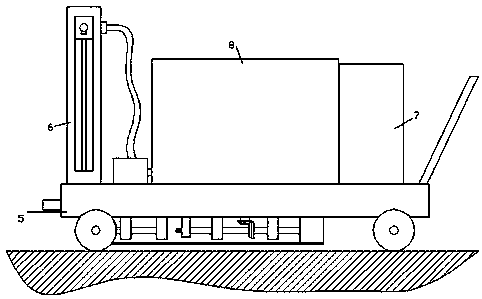
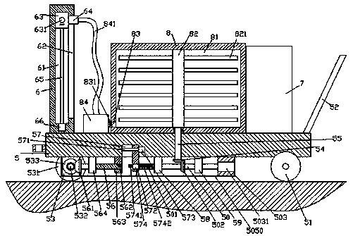
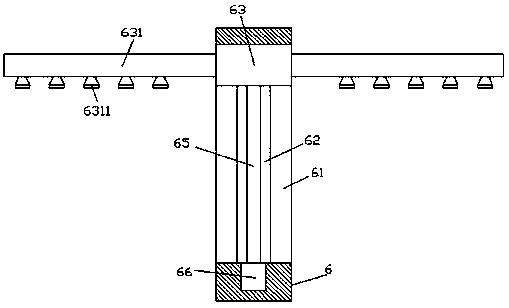
[0025] Such as Figure 1-Figure 5As shown, a practical bridge construction equipment of the present invention includes a frame body 5 and a stirring box 8 fixed at the middle position of the top of the frame body 5, and the top end surface of the frame body 5 on the left side of the stirring box 8 The infusion member 6 is fixedly provided, the top end surface of the frame body 5 on the right side of the agitation box 8 is fixedly provided with an electrification member 7, and the inner middle of the frame body 5 is provided with a first revolving pin shaft 55 which is rotationally fitted and connected. The extension section at the bottom of the first rotating pin shaft 55 grows out of the end face of the bottom of the frame body 5 and the end is fixed with a first cone wheel 54, and the left and right sides of the first cone wheel 54 are respectively provided with a top and a frame The first pole 58 and the second pole 59 fixedly connected to the bottom end surface of the body...


PUM


Abstract

The invention discloses practical bridge construction equipment which comprises a frame body and a stirring box fixed to the middle of the top of the frame body. An infusion component is fixedly arranged on the position, on the left side of the stirring box, of the end face of the top of the frame body, and a power-on component is fixedly arranged on the position, on the right side of the stirringbox, of the end face of the top of the frame body. The middle of the interior of the frame body is provided with a first rotary pin shaft and rotatably connected with the first rotary pin shaft in amatched mode, and bottom extending section of the first rotary pin shaft extends out of the bottom end face of the frame body, and the tail of the bottom extending section of the first rotary pin shaft is fixedly provided with a first cone pulley. A first supporting rod and a second supporting rod with the tops being fixedly connected with the bottom end face of the frame body are arranged on theleft side and the right side of the first cone pulley correspondingly. A third supporting rod is fixedly arranged on the position, on the right side of the second supporting rod, of the bottom end face of the frame body, and a first motor is fixedly arranged in the third supporting rod. The left side end of the first motor is connected with a second rotary pin shaft which is arranged in the mode of extending leftwards. According to the practical bridge construction equipment, the structure is simple, control over switching work can be achieved, various infusion work demands are met, and the working efficiency and effect are improved.

Description

technical field [0001] The invention relates to the technical field of bridges, in particular to practical bridge construction equipment. Background technique [0002] The construction of the bridge pavement requires a large amount of cement slurry. Usually, the cement slurry is poured manually. The manual infusion process is too time-consuming and laborious. It is also poured by a cement slurry truck. However, in some small-scale bridge pavements, cement Although the slurry car has a large capacity, it is not easy to use, and the purchase cost is high. Therefore, an automatic and small cement pouring car is needed during bridge construction. Contents of the invention [0003] The technical problem to be solved by the present invention is to provide a practical bridge construction equipment, which can solve the above-mentioned problems in the prior art. [0004] The present invention is achieved through the following technical solutions: a practical bridge construction eq...

Claims


Application Information

Patent Timeline
Patent Type & Authority Applications(China)
IPC IPC(8): E01D21/00
CPCE01D21/00
Inventor 范苏韩巧女
Owner 广州常佰机械设计有限公司
Why Eureka
Try Eureka