Turbulence structure in array jet cooling

A technology of array jets and jets, which is applied to the supporting elements of blades, engine elements, machines/engines, etc., can solve the problem of unsatisfactory improvement of heat exchange effect, uneven cooling effect of target plate, uneven heat exchange of impacting target plate, etc. problems, to achieve the effect of simple manufacturing process, low flow resistance loss, and reduced impact

Active Publication Date: 2018-06-29
SHENYANG AEROSPACE UNIVERSITY
View PDF2 Cites 9 Cited by
  • Summary
  • Abstract
  • Description
  • Claims
  • Application Information

AI Technical Summary

Problems solved by technology

[0006] (1) After the cooling air flow of the upstream impact hole hits the target plate, a certain amount of cross flow will be generated in the cooling channel, which will affect the downstream jet flow, causing the downstream jet flow to deviate, resulting in uneven cooling effect of the target plate
[0007] (2) After the spoiler element is installed on the target plate of the array ...

Method used


Image

  • Turbulence structure in array jet cooling
  • Turbulence structure in array jet cooling
  • Turbulence structure in array jet cooling

Examples


Embodiment Construction

[0033] The invention will be described in further detail below in conjunction with the accompanying drawings and specific examples, but the present invention is not limited to the following examples.

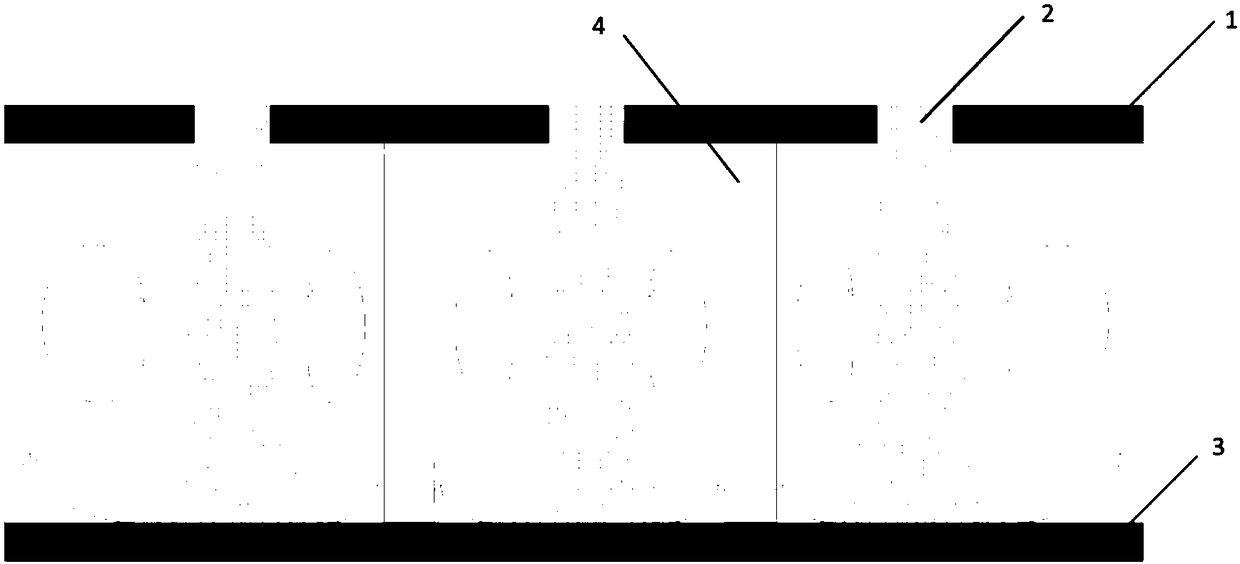
[0034] refer to figure 1 , a highly efficient spoiler column structure in array jet cooling, comprising a jet orifice plate 1 and a jet target plate 3, the jet orifice plate 1 is provided with a plurality of impact holes 2 arranged in an array; the jet orifice plate 1 is located in the The upper part of the jet target plate 3 is designed as a cavity between the two, and the spoiler column 4 is arranged on the jet target plate 3 . In this scheme, the diameter of the impact hole 2 is set to D.

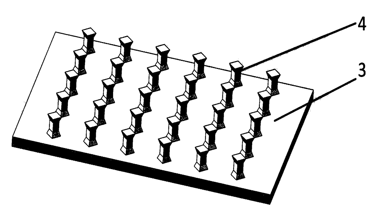
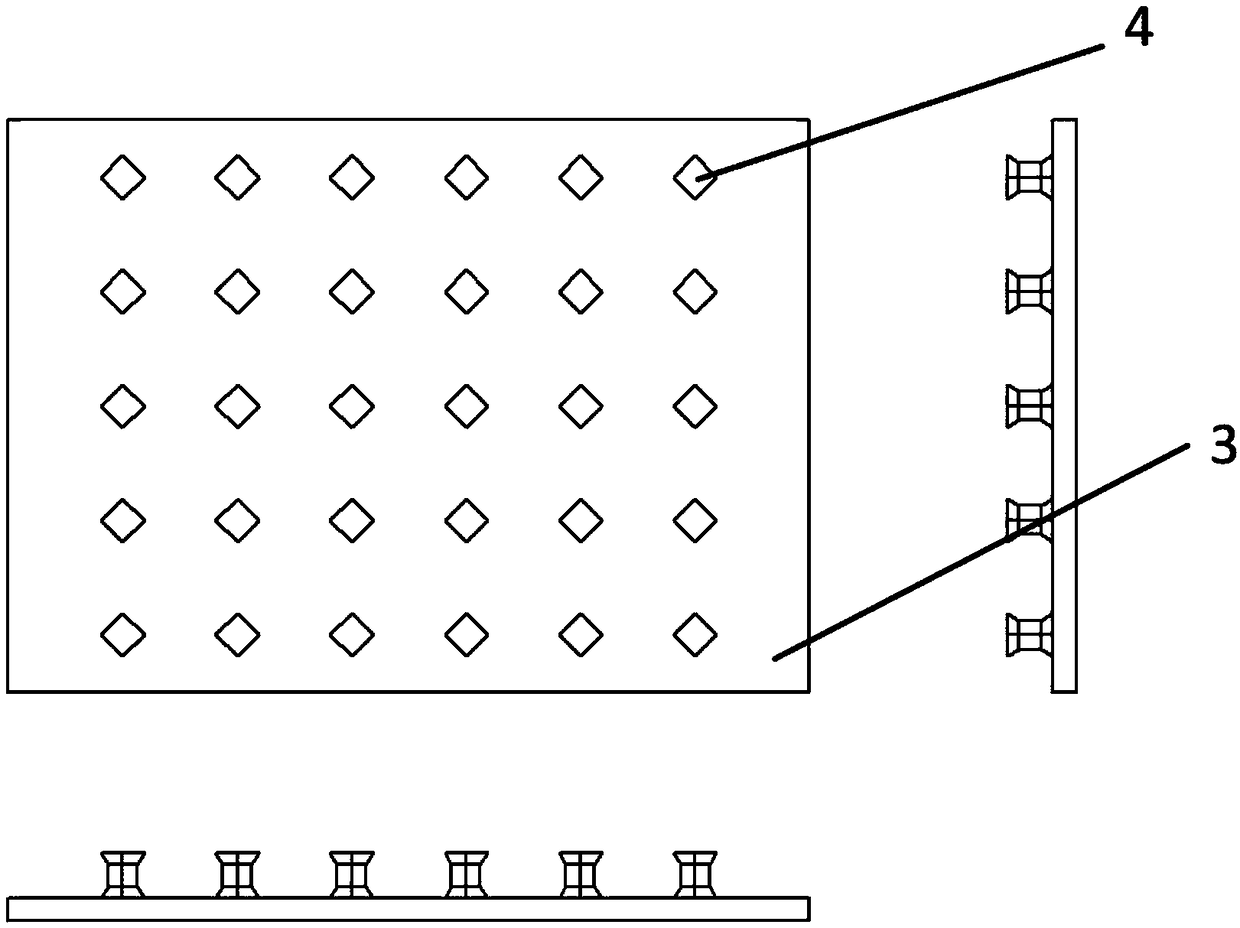
[0035] As a scheme improvement, refer to figure 2 and image 3 , the spoiler column 4 is a quadrangular prism design, and the spoiler column of the quadrangular prism design is divided into upper, middle and lower parts. The top angle is 90°, the side length of the bottom surface is 1...


PUM

PropertyMeasurementUnit
Taperaaaaaaaaaa

Abstract

The invention belongs to the field of cooling of high-temperature parts of gas turbines and aero-engines and some other fields involving array impact jet cooling, in particular to an efficient turbulence column structure in array jet cooling. According to the technical scheme, three turbulence column structure designs are provided, a jet flow target plate with four-prism-shaped turbulence column arranged in an array mode, a jet flow target plate with crescent arc-shaped columnar turbulence columns arranged in an array mode, and a jet flow target plate with dumbbell-shaped turbulence columns arranged in an array mode are comprised. The design has the advantages that the minimum amount of cooling air is used, the cooling efficiency is improved to the maximum degree, the overall temperature gradient of the cooling wall surface is reduced, so that the heat transfer is more uniform and stable.

Description

Technical field: [0001] The invention belongs to the cooling of high-temperature parts of gas turbines and aero-engines and other fields related to array impingement jet cooling, and specifically relates to an efficient turbulence structure in array jet cooling. Background technique: [0002] The gas turbine can provide powerful power mainly through its high-temperature and high-pressure gas. The initial temperature of the high-temperature gas determines the working efficiency of the gas turbine. However, with the increase of gas temperature, the stability and life of the high-temperature components of the gas turbine are severely tested. Now the gas temperature of the first-stage moving blade of the gas turbine turbine has reached above 1800K, such a harsh working environment extremely restricts the working efficiency and life of the gas turbine. Effective cooling techniques must be employed. [0003] At present, the development trend of gas turbines is to increase the te...

Claims


Application Information

Patent Timeline
IPC IPC(8): F01D5/18F01D5/08F01D25/12
CPCF01D5/08F01D5/18F01D25/12F05D2260/201F05D2260/221
Inventor 李润东郭曾嘉贺业光
Owner SHENYANG AEROSPACE UNIVERSITY
Why Eureka
Try Eureka