Engine air intake and exhaust system and method

A technology of air intake and exhaust and engine, which is applied in the direction of engine components, machines/engines, charging systems, etc., can solve the problems of not reaching the theoretical value of fuel combustion, emission not up to standard, and single form, etc., to increase the air intake speed And the intake air volume, the effect of increasing the exhaust gas exhaust velocity and exhaust volume

Inactive Publication Date: 2018-06-29
王陈光
View PDF0 Cites 2 Cited by
  • Summary
  • Abstract
  • Description
  • Claims
  • Application Information

AI Technical Summary

Problems solved by technology

[0002] Existing engine air intake methods include naturally aspirated and turbocharged, and neither the naturally aspirated nor the turbocharged can always guarantee that they can be used in different regions (such as plateau areas, plain areas) and different working conditions (such as There is sufficient air and oxygen supply under conditions such as starting, rapid acceleration, and load), but the theoretical value of fuel combustion cannot be reached, and eventually there will be a series of problems such as substandard emissions, black smoke, engine overheating, and poor economy.
[0003] In order to speed up the engine, the only way currently used is through refueling, which has a single form and is prone to the above problems

Method used


Image

  • Engine air intake and exhaust system and method
  • Engine air intake and exhaust system and method
  • Engine air intake and exhaust system and method

Examples


Embodiment 1

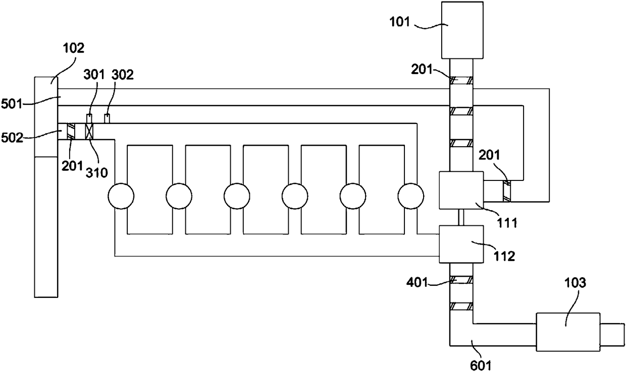
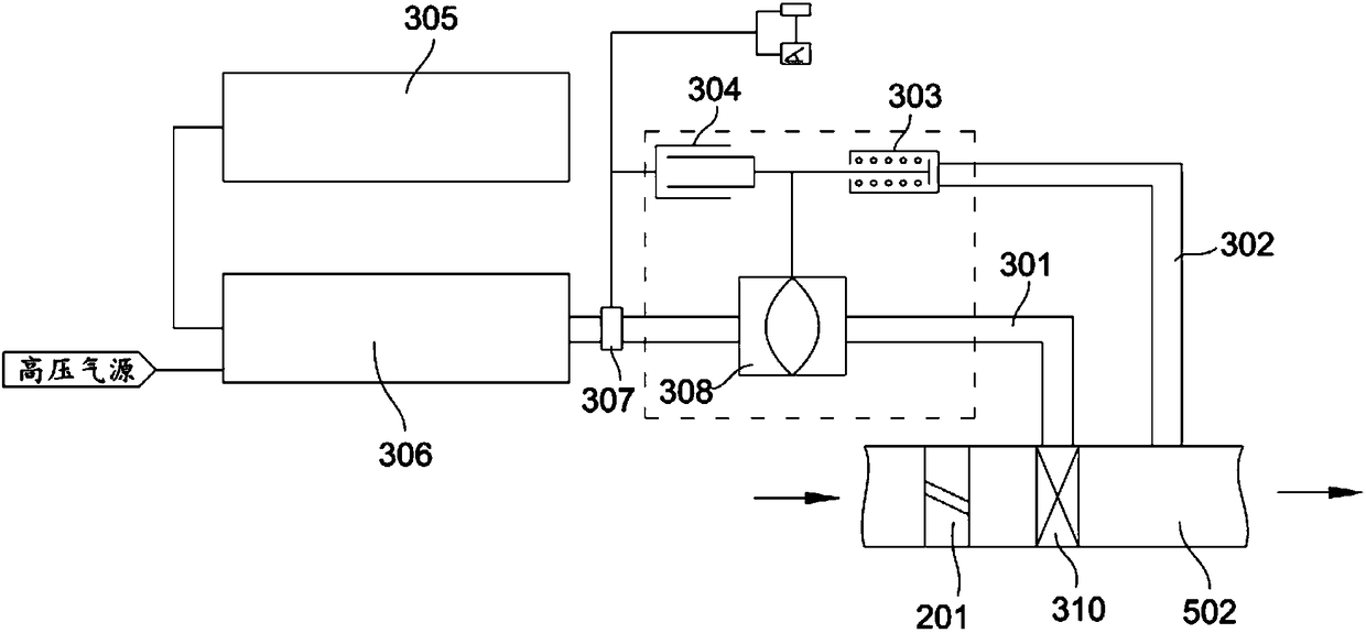
[0046] refer to Figure 1-4 , the engine intake and exhaust system of the present invention includes an intake unit, an exhaust unit and an additional air supply unit, the engine of this embodiment is a turbocharged engine, and the intake unit includes an air filter 101, a compressor of a supercharger The impeller 111, the intercooler 102 and the intake manifold, three intake spoilers 201 are arranged in the first intake pipe 501 between the air filter 101 and the compressor impeller 111 of the supercharger, and the supercharger An intake spoiler 201 is arranged in the first intake pipe 501 between the compressor impeller 111 and the intercooler 102, and an intake spoiler 201 is arranged in the second intake pipe 502 between the intercooler 102 and the intake manifold. An air intake spoiler 201 forms an engine air intake spoiler group through spoilers at three positions. The exhaust unit includes an exhaust manifold, a turbocharger turbine wheel 112 and a muffler 103. In term...

Embodiment 2

[0064] The difference between this embodiment and Embodiment 1 is that this embodiment is for a non-turbocharged engine.

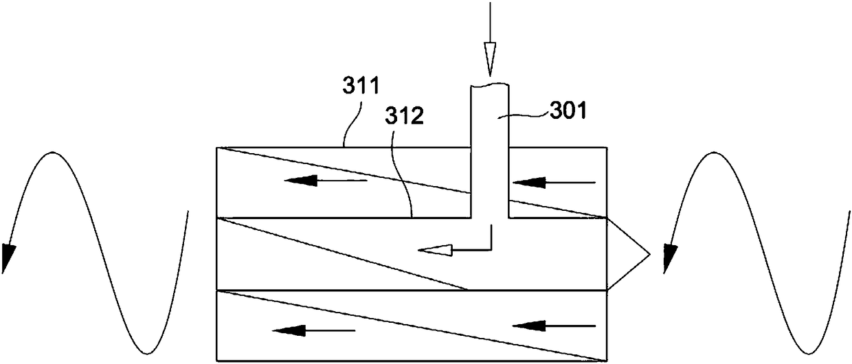
[0065] The air intake unit includes an air filter 101, an intake pipe is connected between the air filter 101 and the intake manifold, and three air intake spoilers 201 are arranged in the intake pipe. Along the airflow direction, the connecting portion of the extra air supply pipe 301 and the intake pipe is located at the rear end of any one of the air intake spoilers 201 . The air entering from the air filter 101 passes through the intake spoiler 201 to achieve acceleration, and at the same time realizes the effect of supercharging and maintaining pressure. The injected high-oxygen gas is mixed and finally enters the engine block for combustion. Due to the increased intake speed and the oxygen content of the incoming air, the fuel in the engine block burns more fully and effectively improves Improve the combustion efficiency of fuel, so that the engine ...


PUM


Abstract

The invention discloses an engine air intake and exhaust system and method. The engine air intake and exhaust system comprises an air intake unit and an exhaust unit. The air intake unit comprises airintake pipes. Air intake spoilers are arranged in the air intake pipes. The exhaust unit comprises an exhaust pipe. Exhaust spoilers are arranged in the exhaust pipe. The air intake spoilers and theexhaust spoilers can enable passing air flow to form rotary air flow. In the engine air intake and exhaust system, the speed of an engine can be increased under the non-refueling condition.

Description

technical field [0001] The invention belongs to the technical field of engines, and in particular relates to an engine intake and exhaust system and method. Background technique [0002] Existing engine air intake methods include naturally aspirated and turbocharged, and neither the naturally aspirated nor the turbocharged can always guarantee that they can be used in different regions (such as plateau areas, plain areas) and different working conditions (such as There is sufficient air and oxygen supply under conditions such as starting, rapid acceleration, and load), but it cannot reach the theoretical value of fuel combustion, and eventually a series of problems such as substandard emissions, black smoke, engine overheating, and poor economy will occur. [0003] In order to increase the speed of the engine, the only way to adopt at present is to realize by refueling, which has a single form and is also prone to the problems mentioned above. Contents of the invention ...

Claims


Application Information

Patent Timeline
IPC IPC(8): F02M35/10F01N13/08
CPCF02M35/10268F01N13/08
Inventor 王陈光
Owner 王陈光
Why Eureka
Try Eureka