High-pressure self-adaptive clearance sealing double-plunger synchronous hydraulic cylinder

A synchronous hydraulic cylinder, self-adaptive technology, applied in the direction of fluid pressure actuating device, servo meter circuit, mechanical equipment, etc. load and improve dynamic performance

Active Publication Date: 2018-06-29
WUHAN UNIV OF SCI & TECH
View PDF3 Cites 0 Cited by
  • Summary
  • Abstract
  • Description
  • Claims
  • Application Information

AI Technical Summary

Problems solved by technology

Such a single-cylinder structure is prone to partial load, which affects the working performance of components and even the system, and shortens the working life of the hydraulic cylinder.

Method used


Image

  • High-pressure self-adaptive clearance sealing double-plunger synchronous hydraulic cylinder
  • High-pressure self-adaptive clearance sealing double-plunger synchronous hydraulic cylinder
  • High-pressure self-adaptive clearance sealing double-plunger synchronous hydraulic cylinder

Examples


Embodiment 1

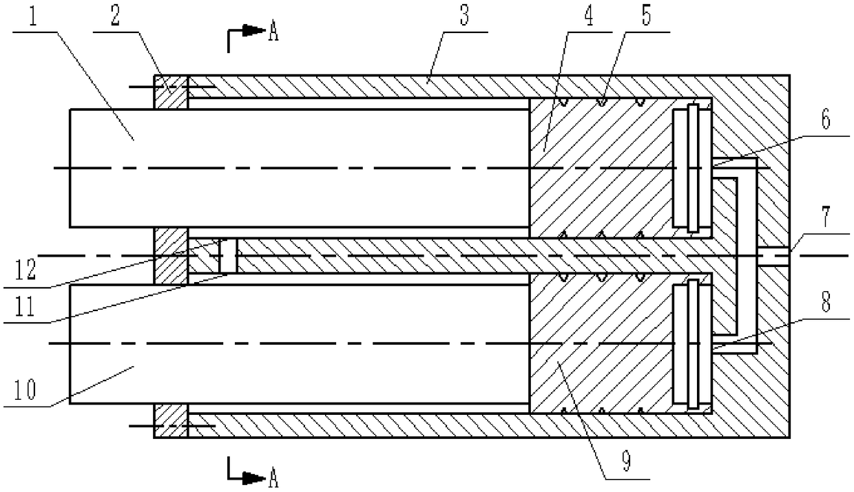
[0026] A high-pressure self-adaptive gap seal double-plunger synchronous hydraulic cylinder. Such as figure 1 with figure 2 As shown, the double-plunger synchronous hydraulic cylinder includes a cylinder barrel 3 , a cylinder head 2 , a first plunger rod 1 , a second plunger rod 10 , a first plunger 4 and a second plunger 9 .

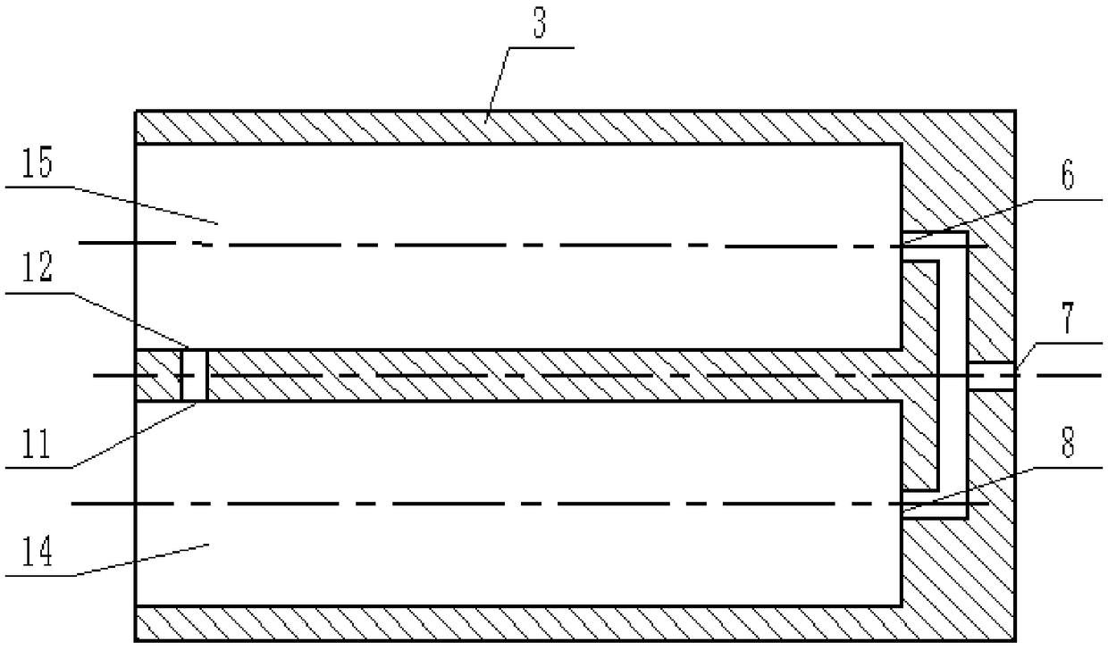
[0027] Such as figure 1 As shown, the first plunger 4 and the second plunger 9 are correspondingly installed in the first plunger chamber 15 and the second plunger chamber 14 of the cylinder 3, the first plunger rod 1 and the second plunger rod 10 It is fixedly connected with the connecting ends of the corresponding first plunger 4 and the second plunger 9, the cylinder head 2 is fixed on the open end of the cylinder barrel 3, and the protruding ends of the first plunger rod 1 and the second plunger rod 10 are respectively Thread out the cylinder head 2.

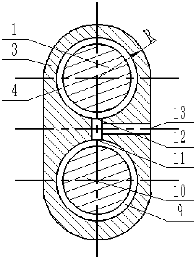
[0028] Such as figure 2 As shown, the cylinder barrel 3 is a cylindrical body of equal sect...

Embodiment 2

[0034] A high-pressure self-adaptive gap seal double-plunger synchronous hydraulic cylinder. Except following technical parameter, all the other are with embodiment 1:

[0035] The distance between the centers of the two semicircles is (2.7~3.0)R;

[0036] lip thickness b =2~3mm, the length of lip a=15~30mm;

[0037] The width a1=1.0~1.2mm of the annular groove, the depth of the annular groove is b1=0.5~0.6mm;

[0038] The cylindrical surface of the cylinder is evenly provided with 4 to 7 pressure equalizing grooves 5;

[0039] The width C of the pressure equalizing groove 5 is 1.0-1.2 mm, and the depth h of the pressure equalizing groove 5 is 0.5-0.6 mm.

[0040] Compared with the prior art, this specific embodiment has the following advantages:

[0041](1) The ends of the first plunger 4 and the second plunger 9 in this specific embodiment are provided with lip edges. When the high-pressure oil entering from the first main oil port 7 enters the first plunger 4 and the...


PUM


Abstract

The invention relates to a high-pressure self-adaptive clearance sealing double-plunger synchronous hydraulic cylinder. According to the technical scheme, a first plunger (4) and a second plunger (9)are installed in a first plunger cavity (15) and a second plunger cavity (14) of a cylinder barrel (3) correspondingly; a first main oil port (7) is formed in the centroid of the outer end face of theclosed end of the cylinder barrel (3) and communicates with a first oil port (6) and a second oil port (8) through an oil channel. A second main oil port (8) is formed in the side face close to the open end of the cylinder barrel (3) and communicates with a third oil port (12) and a fourth oil port (11) through an oil channel. The first plunger (4) and the second plunger (9) are each integrally formed by a cylinder and a lip side at the end of the cylinder. Each lip side is shaped like a circular ring. An annular groove is formed in the middle position of the inner wall of each lip side. Thecylindrical surface of each cylinder is uniformly provided with 3-7 pressure equalization grooves (5). The cross section of each pressure equalization grooves (5) is in a V shape. The high-pressure self-adaptive clearance sealing double-plunger synchronous hydraulic cylinder has the characteristics of being small in size, light in weight, capable of automatically adjusting the clearance sealing amount and capable of effectively preventing unbalance loading and still keeping high volume efficiency.

Description

technical field [0001] The invention belongs to the technical field of double plunger synchronous hydraulic cylinders. In particular, it relates to a high-pressure self-adaptive gap sealing double-plunger synchronous hydraulic cylinder. Background technique [0002] At present, the hydraulic cylinders used in some ports and wharfs are generally single-cylinder types for lifting equipment with long arms, lifting large parts of metallurgical machinery, horizontally pushing heavy equipment, and pushing up gun barrels in military industries. In the case of a large load, when the single-cylinder plunger hydraulic cylinder has an eccentric load in the working process, it is easy to cause partial wear of the plunger and plunger rod and shorten the service life. [0003] When the single-cylinder plunger hydraulic cylinder pushes the long arm, external interference will cause the long arm to swing, which will affect the normal operation of the hydraulic cylinder and easily cause loc...

Claims


Application Information

Patent Timeline
Patent Type & Authority Applications(China)
IPC IPC(8): F15B15/14F15B15/20
CPCF15B15/1409F15B15/1438F15B15/1447F15B15/1457F15B2211/7055F15B2215/30
Inventor 郭媛吴凛傅连东陈新元湛从昌
Owner WUHAN UNIV OF SCI & TECH
Why Eureka
Try Eureka