Signal receiving system and ozone detecting laser radar

A technology for signal receiving and laser detection, which is applied in radio wave measurement systems, measuring devices, electromagnetic wave re-radiation, etc., can solve the problems of low integration, difficult implementation and debugging, and high cost, so as to improve integration and reduce debugging difficulty , cost reduction effect

Pending Publication Date: 2018-06-29
UNIV OF SCI & TECH OF CHINA
View PDF3 Cites 2 Cited by
  • Summary
  • Abstract
  • Description
  • Claims
  • Application Information

AI Technical Summary

Problems solved by technology

[0004] In the prior art, there is no experience for the design of the follow-up receiving optical path of the combined telescope. The traditional design idea for the follow-up receiving optical path of the receiving telescope in the ozone detection lidar system is usually for the echo signal of a single wavelength. A single receiving optical fiber, a set of coupling optical path, a set of photodetector and a set of acquisition device
However, for an ozone detection lidar with a combined telescope, if the follow-up receiving optical path of the combined telescope is still designed according to the traditional design idea, for the echo signal of a single wavelength, it is necessary to design the same number of single telescopes in the combined telescope receiving optical fiber, coupling optical path, photodetector and collection device, then for multiple receiving wavelengths, at least the number of coupling optical paths, photodetectors and collection devices must be multiplied by the number of detection wavelengths on the basis of the above, the combined telescope designed in this way The receiving optical path is not only costly and low in integration, but also difficult to implement and debug later

Method used


Image

  • Signal receiving system and ozone detecting laser radar
  • Signal receiving system and ozone detecting laser radar
  • Signal receiving system and ozone detecting laser radar

Examples


Embodiment Construction

[0055] The following will clearly and completely describe the technical solutions in the embodiments of the application with reference to the drawings in the embodiments of the application. Apparently, the described embodiments are only some of the embodiments of the application, not all of them. Based on the embodiments in this application, all other embodiments obtained by persons of ordinary skill in the art without making creative efforts belong to the scope of protection of this application.

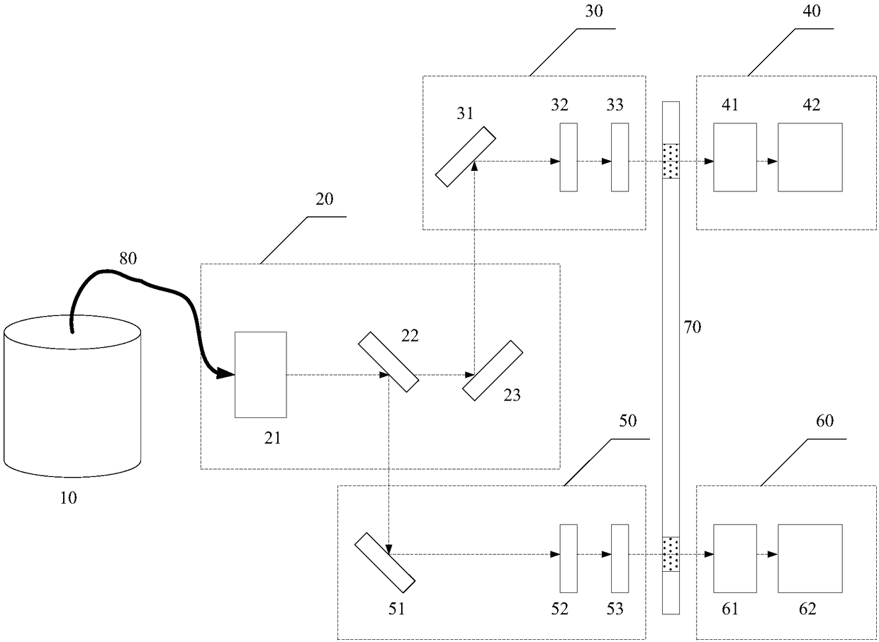
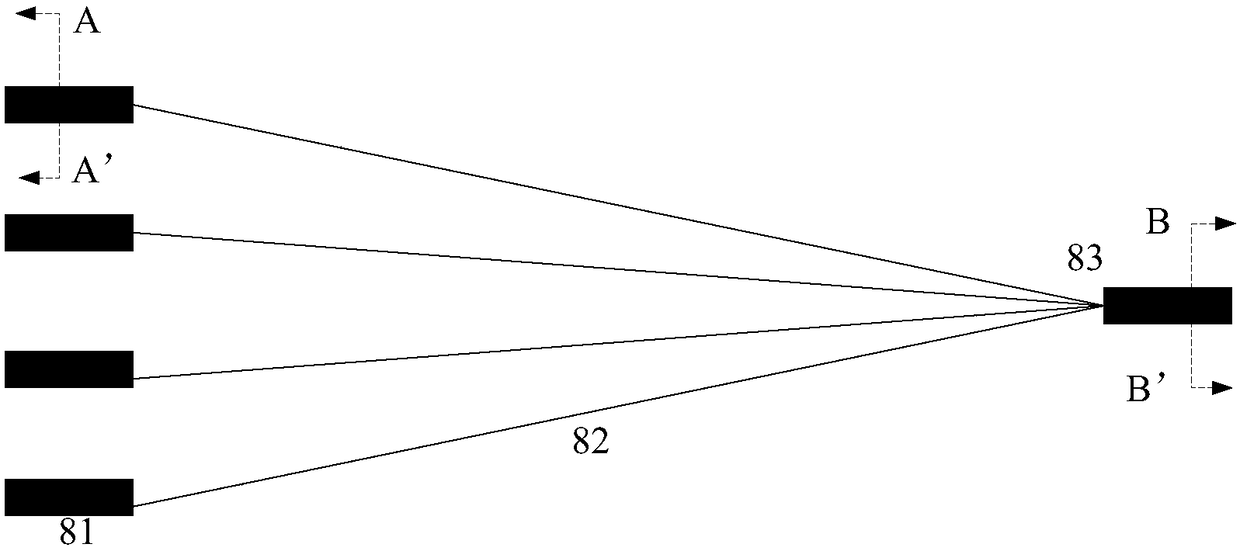
[0056] The embodiment of the present application provides a signal receiving system, such as figure 1 As shown, it is applied to ozone detection lidar, and the signal receiving system includes: combined telescope 10, bundled optical fiber 80, achromatic module 20, first signal processing module 30, second signal processing module 50, first signal conversion module 40. The second signal conversion module 60 and the chopper disc 70; wherein,

[0057] The combined telescope 10 include...


PUM


Abstract

The invention discloses a signal receiving system and an ozone detecting laser radar. The signal receiving system receives ozone echo signals received by a plurality of split telescopes through combined optical fibers and processes the ozone echo signals transmitted by the combined optical fibers through a subsequent light path so that light signals can be converted into electric signals, there isno need to design a large number of coupling light paths, photoelectric detectors or collecting devices according to the number of the split telescopes in a combined telescope, and the aims of reducing the cost of a receiving light path of the combined telescope, improving the integrity of the receiving light path and reducing the adjusting difficulty are realized. In addition, a first signal processing module and a second signal processing module of the signal receiving system are symmetrical about of the axis of a chopper disk, and therefore the photoelectric conversion of Rayleigh echo signals or Raman echo signals can be realized by independently adjusting the light paths where the first signal processing module and the second signal processing module are located.

Description

technical field [0001] The present application relates to the technical field of laser radar systems, and more specifically, to a signal receiving system and ozone detection laser radar. Background technique [0002] In recent decades, lidar has developed rapidly in the field of atmospheric detection, especially in China, where the investment in scientific research has increased, and the development of atmospheric detection lidar has sprung up like mushrooms. In 2012, the National Natural Science Foundation of China funded the national major scientific research equipment development project "multi-band multi-atmospheric component active and passive comprehensive detection system", which includes multiple lidar sub-projects, such as aerosol cloud lidar, Rayleigh sodium Wind temperature lidar, ozone detection lidar, pollutant detection lidar, carbon dioxide lidar, etc. Among them, the Rayleigh sodium wind temperature lidar and the ozone detection lidar need to detect the midd...

Claims


Application Information

Patent Timeline
Patent Type & Authority Applications(China)
IPC IPC(8): G01S7/481G01S17/95
CPCG01S7/4816G01S7/4818G01S17/95Y02A90/10
Inventor 方欣李陶
Owner UNIV OF SCI & TECH OF CHINA
Why Eureka
Try Eureka