A kind of laser radar and its laser pulse timing adjustment method

A laser pulse and lidar technology, applied in radio wave measurement systems, instruments, etc., can solve the problems of poor laser ranging effect and uneven scanning, and achieve the effect of light weight, large scanning field of view, and good imaging effect.

Active Publication Date: 2019-07-12
CHINA AIR TO AIR MISSILE INST
View PDF1 Cites 0 Cited by
  • Summary
  • Abstract
  • Description
  • Claims
  • Application Information

AI Technical Summary

Problems solved by technology

[0007] The object of the present invention is to provide a laser radar and its laser pulse timing adjustment method to solve the problem of poor laser ranging effect caused by the uneven scanning of the Lissajous pattern scanning method

Method used


Image

  • A kind of laser radar and its laser pulse timing adjustment method
  • A kind of laser radar and its laser pulse timing adjustment method
  • A kind of laser radar and its laser pulse timing adjustment method

Examples


Embodiment Construction

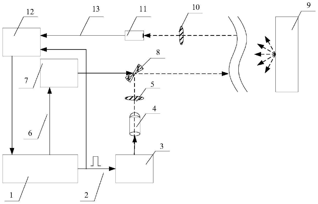
[0049] The present invention provides a laser radar, which is a miniature laser radar, and the schematic diagram of the mechanism corresponding to the best embodiment of the laser radar is as follows figure 1 As shown, the solid line in this figure represents the electrical signal, and the dotted line represents the optical signal.

[0050] The lidar includes a programmable gate array FPGA 1 and a signal processing module 12, which are the core control and processing units of the lidar.

[0051] Wherein, the programmable gate array FPGA 1 is used to emit a trigger pulse, and at the same time, the trigger pulse signal is also used as a timing start signal for laser ranging, and the start signal is sent to the signal processing module 12 . The signal processing module 12 receives the echo reflected or scattered by the target 9 , and calculates the time difference between the start signal and the received echo, as well as the strength of the echo signal, and transmits it to the ...


PUM


Abstract

The invention relates to a laser radar and its laser pulse timing adjustment method. By continuously adjusting the set threshold and / or the minimum time interval between adjacent laser pulses, there are at least A Lissajous scanning point can effectively obtain the emission timing of the laser pulse and the mapping relationship with the pixel position. When laser pulses are emitted according to this sequence, the target can be scanned stably and uniformly, which overcomes the shortcomings of Lissajous scanning such as sparse center and dense surrounding, thus making the scanning result clearer.

Description

technical field [0001] The invention belongs to the technical field of laser radar, and in particular relates to a laser radar and a laser pulse timing adjustment method thereof. Background technique [0002] Lidar is a radar system that emits laser beams to detect the position, speed and other characteristic quantities of the target. Its imaging methods include non-scanning imaging and scanning imaging. [0003] Non-scanning imaging has no mechanical scanning device, and has the characteristics of high frame rate, wide field of view, robustness, and small size. It is a development trend of LiDAR in the future. However, non-scanning imaging requires that the laser’s emission power is sufficiently large, and the technology of the two-dimensional receiving detector is complex and expensive. Laser non-scanning imaging received by an image-enhanced charge-coupled device (ICCD) needs to cooperate with range gating technology to obtain the corresponding distance information. And ...

Claims


Application Information

Patent Timeline
Patent Type & Authority Patents(China)
IPC IPC(8): G01S7/484G01S7/481
CPCG01S7/4817G01S7/484
Inventor 高挺挺周树平穆学桢谢光辉彭志永严毅雷卫宁潘辉
Owner CHINA AIR TO AIR MISSILE INST
Why Eureka
Try Eureka