
Rotary laser scanning device

A laser scanning device and rotary technology, applied in the field of laser scanning, can solve the problems of difficult laser emission angle deflection scanning, unsatisfactory scanning effect, etc., and achieve the effect of broadening the application range, fast and efficient scanning mode, and simple structure

Pending Publication Date: 2018-06-29
深圳市砝石激光雷达有限公司
View PDF1 Cites 13 Cited by
  • Summary
  • Abstract
  • Description
  • Claims
  • Application Information

AI Technical Summary

Problems solved by technology

This kind of device uses a moving mirror to cooperate, often requires more mechanism cooperation, and the scanning effect is not ideal
Moreover, these scans are linear scans, and it is difficult to deflect the angle of laser emission

Method used


Image

  • Rotary laser scanning device
  • Rotary laser scanning device
  • Rotary laser scanning device

Examples


Embodiment Construction

[0019] The present invention will be described in detail below in conjunction with specific embodiments and accompanying drawings.

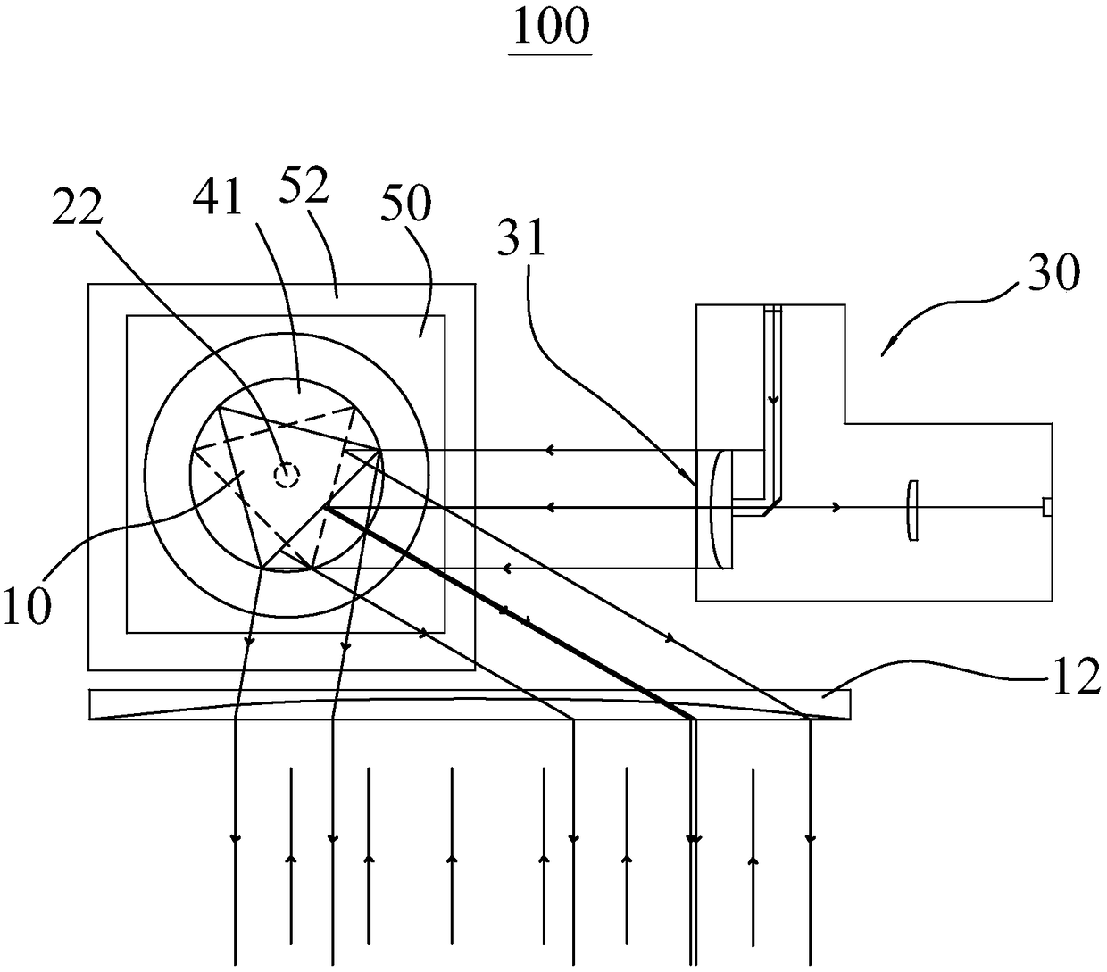
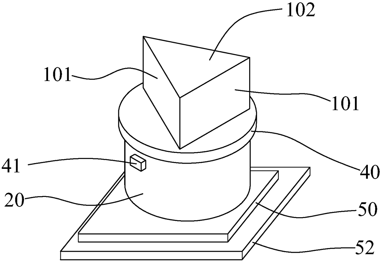
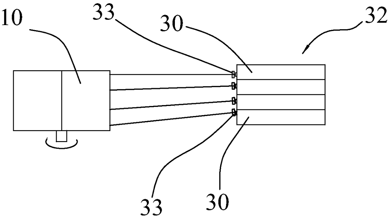
[0020] Please refer to the example figure 1 and 2 , shows a rotary laser scanning device 100 provided in this embodiment, including a rotary prism 10, a rotary drive member 20, and a laser 30, the laser 30 has a laser transceiver end 31, and the rotary prism 10 has a plurality of side prisms surface 101, the rotary drive member 20 is connected with the rotary prism 10 to drive the rotary prism 10 to rotate, and when the rotary prism 10 rotates, each side prism surface 101 rotates to the position facing the laser transceiver end 31 in turn, and at this position At this time, the laser light emitted by the laser device 30 and the returned laser light are reflected to deflect the laser light emission direction by a predetermined angle, and to rotate and scan.

[0021] Specifically, the rotating drive member 20 is a motor, and the rotating prism 10...


PUM


Abstract

The invention relates to a rotary laser scanning device. The device comprises a rotary prism, a rotary drive part and a laser, wherein the laser comprises a laser receiving and transmitting end, the rotary prism comprises multiple side edge surfaces, the rotary drive part is connected with the rotary prism to drive the rotary prism to rotate, during rotation of the rotary prism, all side edge surfaces are sequentially rotated to the position opposite to the laser receiving and transmitting end, and laser emitted by the laser and returned laser are reflected in the position are reflected, so that the laser emergent direction is deflected by a preset angle, and rotary scanning is performed. During rotation of the rotary prism, all the side edge surfaces sequentially reflect laser, thus, thelaser radar scanning effect can be realized through cooperation of one laser with the rotary prism, the structure is convenient, and the scanning manner is quick and efficient. Besides, the emergent angle of the laser is deflected through the rotary prism, and the rotary laser scanning device can be widely applied to the fields of obstacle avoidance and navigation for a driving assistance system,an unmanned driving system, a mobile robot and an unmanned aircraft.

Description

technical field [0001] The invention relates to the technical field of laser scanning, in particular to a rotary laser scanning device. Background technique [0002] With the development of laser technology, laser scanning technology is more and more widely used in surveying, transportation, driving assistance and drones, mobile robots and other fields. Existing laser scanning radars generally have high manufacturing costs and complex structures, and some have large volume and mass, which is not conducive to the application of laser radar in driving assistance systems, unmanned driving systems, mobile robots, unmanned aircraft obstacle avoidance and Applications in the field of navigation. [0003] Laser scanning is mainly through the rapid and continuous emission of multiple pulses. The direction of these emission changes continuously in a certain way, and each distance measurement value is regarded as a pixel. The collection of fast and continuous emission and recorded ...

Claims


Application Information

Patent Timeline
IPC IPC(8): G02B26/12G02B26/10
CPCG02B26/105G02B26/123
Inventor 刘庆京蒋柏娴蒋伟
Owner 深圳市砝石激光雷达有限公司
Learn More