
Open-loop CONTROL unit or closed-loop control unit for A MOULDING MACHINE

A technology of open-loop control and closed-loop control, applied in general control systems, adaptive control, control/regulation systems, etc., can solve problems such as non-optimized and too slow trajectories, and achieve the effect of optimized trajectories

Pending Publication Date: 2018-06-29
ENGEL AUSTRIA
View PDF6 Cites 0 Cited by
  • Summary
  • Abstract
  • Description
  • Claims
  • Application Information

AI Technical Summary

Problems solved by technology

This in turn leads to unoptimized optimization results, e.g. too slow trajectories in case of pure time optimization

Method used


Image

  • Open-loop CONTROL unit or closed-loop control unit for A MOULDING MACHINE
  • Open-loop CONTROL unit or closed-loop control unit for A MOULDING MACHINE
  • Open-loop CONTROL unit or closed-loop control unit for A MOULDING MACHINE

Examples


Embodiment Construction

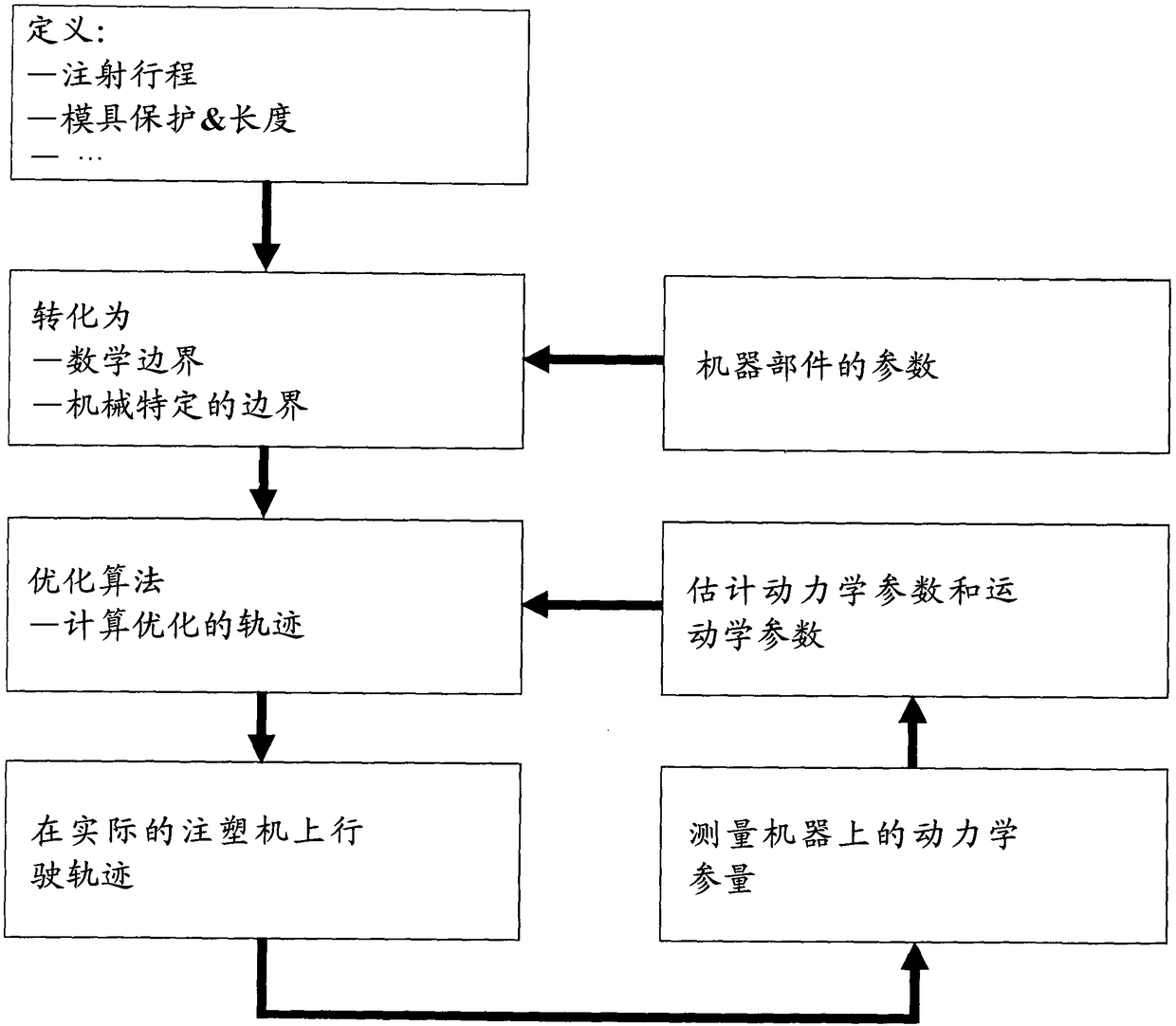
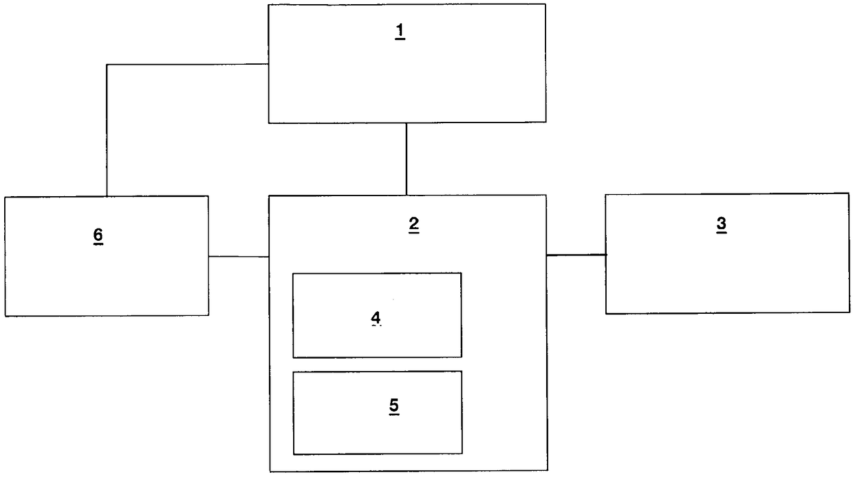
[0044] The molding machine 1 is given in the form of an electric crank lever machine, which not only performs a mold clamping movement with the aid of a crank lever, but also generates a clamping force (through a suitable transmission ratio of the crank lever). The mold clamping movement and the generation of the mold clamping force should be performed optimally based on different criteria and taking into account certain boundary conditions.

[0045] Here, the possible boundary conditions are:

[0046] -The desired mold stroke (injection stroke), which is given in advance by the operator and determined by the mold and its characteristics.

[0047] ——Machine limits, such as the maximum motor torque, the current in the motor and the inverter, the maximum movement speed and the change in speed or the change in acceleration in mechanical parts such as the shaft and bearings.

[0048] ——Mold protection, that is, the maximum speed of the mold at the closing time and the maximum speed distri...


PUM


Abstract

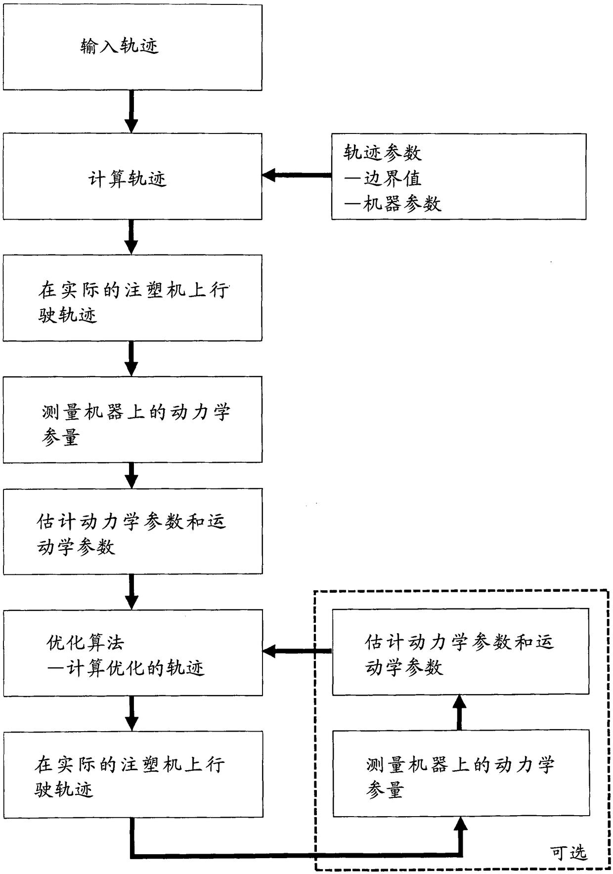
The invention relates to a method for open-loop control or closed-loop control of a closing mechanism of a moulding machine, a motion mechanism enables a movable mould clamping plate to move, a firsttrajectory of movement of the movable mould clamping plate under open-loop or closed-loop control is calculated using a first algorithm based on operator inputs relating to the desired movement of themovable mould clamping plate and particularly predefined parameter values of a dynamic or kinematic parameter of the closing mechanism, and the movable mould clamping plate is moved under open-loop or closed-loop control according to the first trajectory. The dynamic or kinematic parameter of the closing mechanism is measured during the movement of the movable mould clamping plate according to the first trajectory, and an estimate of the parameter value is generated based on the measurement. A second trajectory of movement of the movable mould clamping plate under open-loop or closed-loop control is calculated using an optimization algorithm based on the estimate, and the movable mould clamping plate is moved under open-loop or closed-loop control according to the second trajectory. The invention also relates to a moulding machine.

Description

Technical field [0001] The present invention relates to a method for open-loop control or closed-loop control of a mold clamping mechanism of a molding machine with the features of the preamble of claim 1, in which a movement mechanism moves a movable mold clamping plate; And the present invention relates to a molding machine having the features of the preamble of claim 3. Background technique [0002] A method of the same type and a molding machine of the same type are known from AT 502 382 B1. [0003] The basic functions of the optimization algorithm used to calculate the mathematically optimized trajectory according to AT 502 382 B1 (take the electroforming machine as an example, the method can also be used for the hydraulic forming machine) as follows: [0004] -Optimized program model: [0005] ·The dynamic model of the crank lever, the model includes all the required mass and inertia, such as the mass and inertia of the lever, the driving part and the mold clamping plate; [00...

Claims


Application Information

Patent Timeline
IPC IPC(8): G05B13/04
CPCB29C45/766B29C2945/76913B29C2945/76598B29C2945/76602B29C2945/76568G05B13/041B29C45/80B29C2945/76936B29C45/7653B29C45/661
Inventor K·斯普林格F·J·基利安
Owner ENGEL AUSTRIA
Learn More