
High-temperature fuel cell system and operating method thereof

A high-temperature fuel cell and operating method technology, applied in the direction of fuel cells, fuel cell additives, fuel cell control, etc., can solve problems such as limited fan performance, accelerated material machinery, and loss of phosphoric acid in batteries to achieve improved uniformity and Consistency, accelerated mechanical aging, and reduced aging effects

Active Publication Date: 2018-06-29
DALIAN INST OF CHEM PHYSICS CHINESE ACAD OF SCI
View PDF4 Cites 8 Cited by
  • Summary
  • Abstract
  • Description
  • Claims
  • Application Information

AI Technical Summary

Problems solved by technology

[0003] During the start-up process of a high-temperature fuel cell system, the battery stack needs to be heated to the operating temperature before the battery can be discharged. However, due to its high operating temperature, the uniform and efficient heating of the battery stack has an important impact on the performance and life of the fuel cell stack. However, the traditional electric heating method will cause a large difference in the internal temperature of the battery stack during the start-up process of the high-temperature fuel cell, which will accelerate the mechanical aging of the material, thereby affecting the performance and life of the high-temperature fuel cell system.
[0004] However, during the operation of the high-temperature fuel cell system, since the system emits a large amount of heat when operating at high power, the traditional fan cooling method will cause problems such as the limited performance of the fan itself and the serious loss of phosphoric acid in the battery due to excessive air volume. The system cannot dissipate heat effectively or the performance degrades sharply

Method used


Image

  • High-temperature fuel cell system and operating method thereof
  • High-temperature fuel cell system and operating method thereof
  • High-temperature fuel cell system and operating method thereof

Examples


specific Embodiment approach

[0038] Specific implementation methods include:

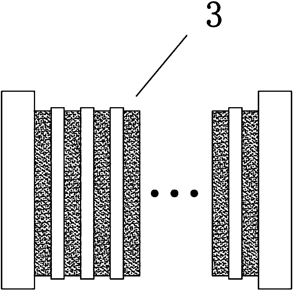
[0039] Bipolar plate 1 is used for fluid distribution and heat transfer oil circulation; membrane electrode assembly 2 is a component unit of fuel cell stack; fuel cell stack 3 is used to convert fuel into electrical energy; heat transfer oil heating device 4 is used for fuel The heat transfer oil flowing in the battery stack system is heated; the heat transfer oil drives the pump to drive the flow of heat transfer oil in the system.

[0040] working principle:

[0041] The high-temperature proton exchange membrane fuel cell uses PBI or TBS membrane, and its proton transmission does not depend on the effect of water, so it can be used at a relatively high temperature. This implementation method uses flowing heat transfer oil to heat the cell stack 3 , the flowing heat-conducting oil enters the battery cell stack 3 after being heated in the heat-conducting oil heating device to heat the battery cell stack 3 . During the flow o...

specific Embodiment approach 1

[0044] Embodiment 1: The heat transfer oil heating device 4 adopts a serpentine flow field structure to ensure the residence time of the heat transfer oil in the heat transfer oil heating device 4 and achieve the effect of sufficient heat exchange. The heat transfer oil heating device 4 is heated by electric heating, and the heat transfer oil uses a heat transfer oil to drive a pump to promote the circulation of the heat transfer oil. The heat transfer oil with a lower temperature enters the heat transfer oil heating device 4 for heating under the drive of the driving pump, and the heated heat transfer oil enters the fuel cell stack 3 to heat the fuel cell stack 3 . The heat transfer oil that has fully exchanged heat in the fuel cell stack 3 and flows out of the fuel cell stack 3 enters the heat transfer oil heating device 4 again for heating under the drive of the heat transfer oil driving pump, thus forming a cycle and realizing the start-up of the fuel cell stack 3 The proc...

specific Embodiment approach 2

[0045] Specific implementation mode 2: The heat transfer oil heating device 4 adopts a parallel flow field structure, and the diameter of the flow channel is 1mm, so as to ensure that the heat transfer oil is heated evenly everywhere. The heat transfer oil heating device 4 uses the high-temperature tail gas of the reformer to heat it, and the heat transfer oil uses the heat transfer oil to drive the pump to promote the circulation of the heat transfer oil. The heat transfer oil with a lower temperature enters the heat transfer oil heating device 4 for heating under the drive of the driving pump, and the heated heat transfer oil enters the fuel cell stack 3 to heat the fuel cell stack 3 . The heat transfer oil that has fully exchanged heat in the fuel cell stack 3 and flows out of the fuel cell stack 3 enters the heat transfer oil heating device 4 again for heating under the drive of the heat transfer oil driving pump, thus forming a cycle and realizing the start-up of the fuel ...


PUM


Abstract

The invention provides a high-temperature fuel cell system and an operating method thereof. The high-temperature fuel cell system comprises a high-temperature fuel cell pile and a heat conducting oilpre-heater; a first heat conducting oil flowing channel with an inlet and an outlet is formed in the heat conducting oil pre-heater; a second heat conducting oil flowing channel is formed in a single-cell bipolar plate; a closed heat conducting oil loop is formed after the first heat conducting oil flowing channel communicates with the second heat conducting oil flowing channel; a fluid flowing driving part and a flow adjusting part are arranged on the closed heat conducting oil loop. The operating method comprises the following steps: heating the heat conducting oil pre-heater through a firstheating device; heating the high-temperature fuel cell pile through heated heat conducting oil; detecting the temperature of the high-temperature fuel cell pile in real time through a pile temperature detecting part; when the temperature of the pile reaches a preset value T1, starting the high-temperature fuel cell pile. According to the high-temperature fuel cell system and the operating methodthereof, the problem of non-uniform heating caused by electric heating during a starting process of a fuel cell can be solved effectively.

Description

technical field [0001] The invention relates to the technical field of fuel cells, in particular to a high-temperature fuel cell system with a preheating function. Background technique [0002] A fuel cell is a device that converts chemical energy stored in compound fuels directly into electrical energy through a chemical reaction. A proton exchange membrane fuel cell usually consists of an anode, a cathode and a proton exchange membrane. During the operation of the battery, the fuel undergoes an oxidation reaction on the surface of the anode catalyst to generate protons and electrons. The protons reach the cathode through the proton exchange membrane, oxygen undergoes a reduction reaction with the protons on the surface of the cathode catalyst to generate water, and the electrons do work through the external circuit to reach the cathode. [0003] During the start-up process of a high-temperature fuel cell system, the battery stack needs to be heated to the operating temper...

Claims


Application Information

Patent Timeline
Patent Type & Authority Applications(China)
IPC IPC(8): H01M8/04302H01M8/04007H01M8/04029H01M8/249H01M8/0432H01M8/04701
CPCH01M8/04029H01M8/04037H01M8/04298H01M8/0432H01M8/04701H01M8/249Y02E60/50
Inventor 孙公权孙雪敬杨林林孙海
Owner DALIAN INST OF CHEM PHYSICS CHINESE ACAD OF SCI
Learn More