
Antenna element and array antenna

An antenna unit and array antenna technology, applied in the field of communication, can solve the problems that antenna devices cannot cover all frequency bands, reduce antenna directivity, and low gain ratio, and achieve high integration and miniaturization requirements, increase antenna gain, and expand The effect of wideband bandwidth

Active Publication Date: 2018-06-29
AAC PRECISE MFG TECH CHANGZHOU
View PDF6 Cites 3 Cited by
  • Summary
  • Abstract
  • Description
  • Claims
  • Application Information

AI Technical Summary

Problems solved by technology

[0003] Taking mobile phones as an example, the antenna device of the related technology is embedded in the mobile phone, which includes a ground plane and a feed point electrically connected to the ground plane. With the pursuit of miniaturization of mobile phones, the volume of mobile phones is getting smaller and smaller. The volume of the antenna device embedded in the mobile phone is also getting smaller and smaller, and the distance between the feed point in the antenna device and the ground plate becomes smaller, resulting in a decrease in the frequency band range of the antenna device.
With the further miniaturization of the volume of mobile communication devices such as mobile phones, the volume of the antenna device continues to decrease, so that the antenna device of the related technology will not be able to cover all the frequency bands required for GSM global roaming, which greatly affects the communication function of global roaming
[0004] In order to solve the above technical problems, a relatively small array antenna is embedded in a common mobile phone at present, but the inventors of the present invention have found that the array antenna embedded in a mobile phone in the prior art usually adopts the form of a slot Although the array antenna in the form of patch and slot form is easy to process and realize, it will reduce the directivity of the antenna to a certain extent because of its low gain ratio in the antenna radiation direction in the setting, and in order to ensure that the array antenna has a high gain, its footprint needs to be larger
Although the existing patch-type array antenna occupies a small area, the preparation process is complicated and the gain is low, which cannot meet the needs of users at all.

Method used


Image

  • Antenna element and array antenna
  • Antenna element and array antenna
  • Antenna element and array antenna

Examples


Embodiment Construction

[0025] In order to make the object, technical solution and advantages of the present invention clearer, various embodiments of the present invention will be described in detail below in conjunction with the accompanying drawings. However, those of ordinary skill in the art can understand that in each implementation manner of the present invention, many technical details are proposed in order to enable readers to better understand the present invention. However, even without these technical details and various changes and modifications based on the following implementation modes, the technical solution claimed in the present invention can also be realized.

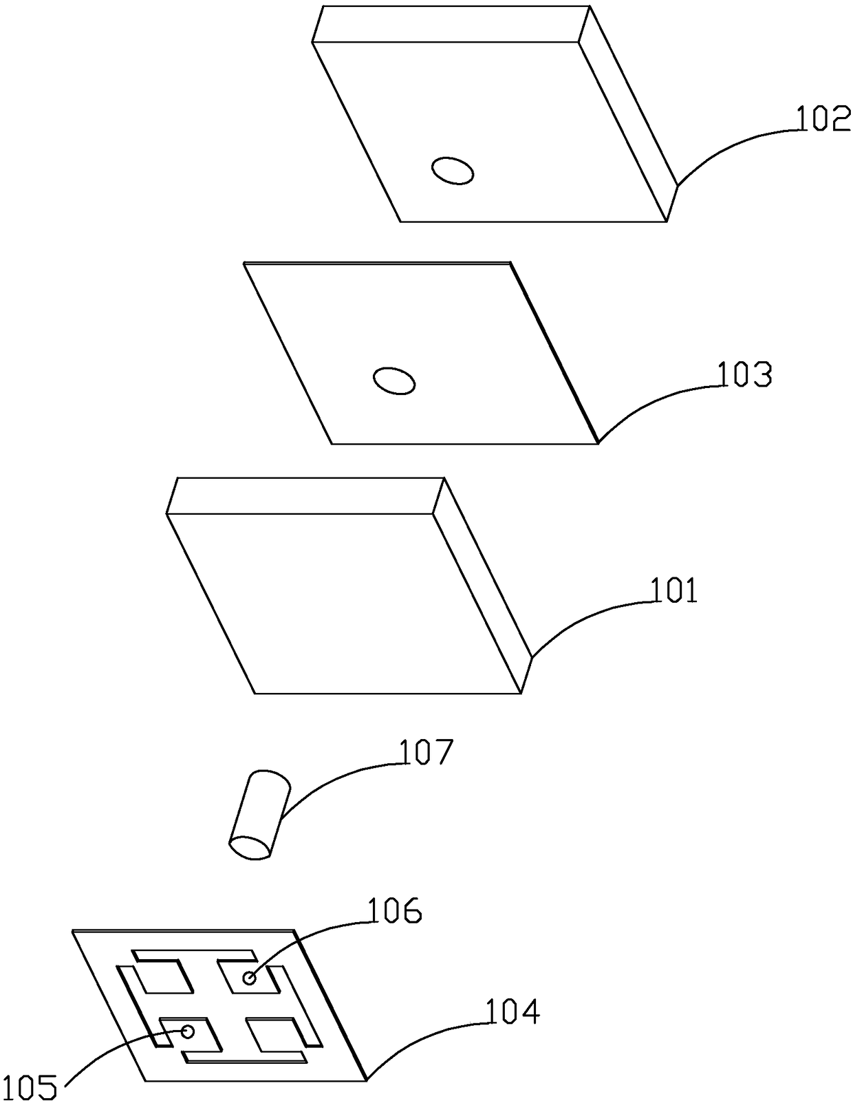
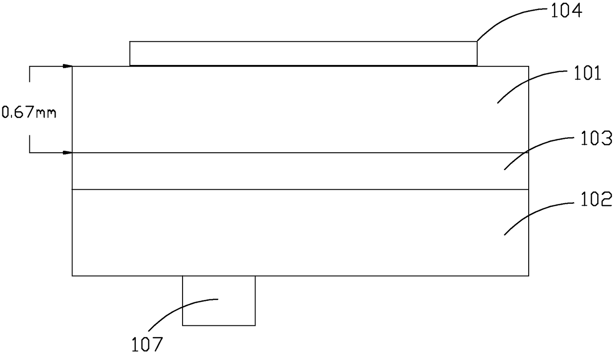
[0026] A first embodiment of the present invention relates to an antenna unit. like figure 1 , figure 2 As shown, the antenna unit 100 includes a first dielectric layer 101 , a second dielectric layer 102 , a ground patch 103 and a radiation patch 104 .

[0027] Wherein, the first dielectric layer 101 , the ground sheet...


PUM

PropertyMeasurementUnit
Thicknessaaaaaaaaaa

Abstract

The invention relates to the communication field and discloses an antenna element and an array antenna. The antenna element comprises a first dielectric layer, a second dielectric layer, a ground strap and a radiation patch, wherein the first dielectric layer, the ground strap and the second dielectric layer are sequentially arranged from top to bottom, the radiation patch is arranged at the top of the first dielectric layer; an open slot is formed in the radiation patch, and a feeding point and a ground point are arranged on the radiation patch and at the two opposite sides of the open slot respectively; and the feeding point runs through the first dielectric layer, the ground strap and the second dielectric layer by virtue of a coaxial line, and the ground point is connected with the ground strap. Compared with the prior art, the antenna element and the array antenna which are provided by the invention have the advantages of high gain, low sidelobe level, broadband and miniaturization at the same time, and the high integratability and miniaturization demand of the whole antenna structure can be effectively realized.

Description

technical field [0001] The invention relates to the communication field, in particular to an antenna unit and an array antenna. Background technique [0002] With the rapid development of communication technology, there are more and more wireless mobile devices, especially mobile phones. People are not only satisfied with simple call functions, but also pursue miniaturization and communication quality of mobile communication devices such as mobile phones. The use of the antenna device therein as an important part of the communication quality has attracted more and more attention in its development. [0003] Taking mobile phones as an example, the antenna device of the related technology is embedded in the mobile phone, which includes a ground plane and a feed point electrically connected to the ground plane. With the pursuit of miniaturization of mobile phones, the volume of mobile phones is getting smaller and smaller. The volume of the antenna device embedded in the mobil...

Claims


Application Information

Patent Timeline
IPC IPC(8): H01Q1/38H01Q1/48H01Q1/50H01Q21/08H01Q1/24
CPCH01Q1/243H01Q1/38H01Q1/48H01Q1/50H01Q21/08
Inventor 许心影
Owner AAC PRECISE MFG TECH CHANGZHOU
Features
  • Generate Ideas
  • Intellectual Property
  • Life Sciences
  • Materials
  • Tech Scout
  • Unparalleled Data Quality
  • Higher Quality Content
  • 60% Fewer Hallucinations
Learn More