Reinforced rotational-flow sand setting tank

A cyclone sand settling and tank body technology, applied in chemical instruments and methods, water pollutants, centrifugal separation of water/sewage treatment, etc. Enhance the effect of swirl

Active Publication Date: 2018-07-03
PETROCHINA CO LTD
View PDF5 Cites 5 Cited by
  • Summary
  • Abstract
  • Description
  • Claims
  • Application Information

AI Technical Summary

Problems solved by technology

[0005] The above-mentioned Zhong’s and Bi’s grit chambers require power equipment and power consumption during operation; power equipment and internal blades

Method used


Image

  • Reinforced rotational-flow sand setting tank
  • Reinforced rotational-flow sand setting tank
  • Reinforced rotational-flow sand setting tank

Examples


Embodiment 1

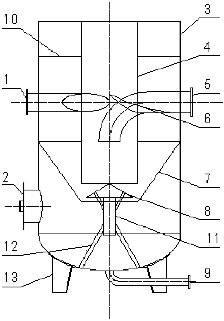
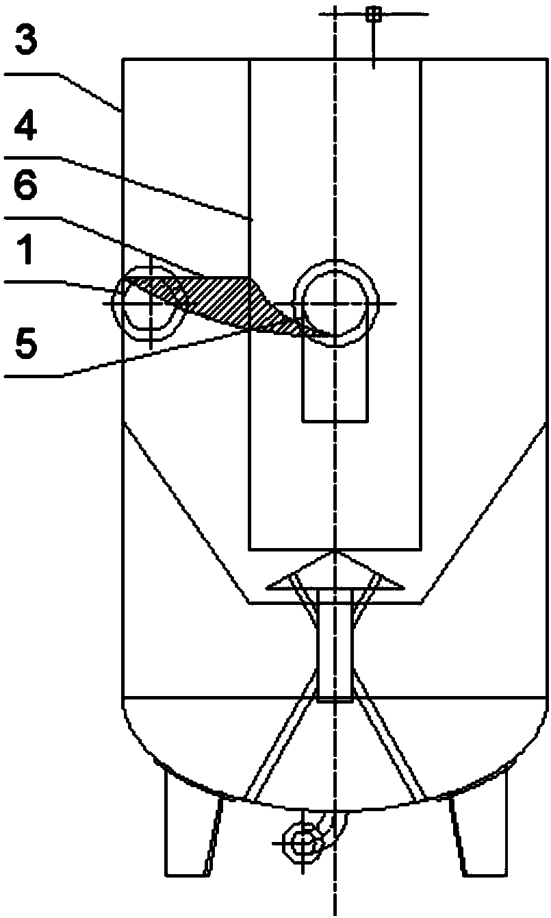
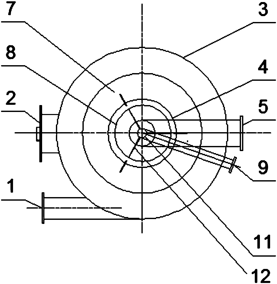
[0032] see Figure 1-7 As shown, the enhanced cyclone grit chamber of the present invention includes a tank body 3, the upper part of the tank body 3 is provided with a water inlet pipe 1 and a water outlet pipe 5, and the connection between the water inlet pipe 1 and the water outlet pipe 5 and the tank body 3 is a water inlet respectively. (not marked) and the water outlet (not marked), the outlet pipe 4 continues to pass through the inner cylinder 4 to extend to its inside, the bottom of the tank body 3 is provided with a manhole 2, and the bottom of the tank body 3 is provided with a sand discharge pipe 9, the tank body The inside of 3 is provided with inner cylinder 4, annular inclined plate 7 and deflector cap 8 from top to bottom, and deflector 6 is arranged between inner cylinder 4 and tank body 3, and deflector 6 is helical (similar to helical blade ), one end of the deflector 6 is located above the water inlet, the other end is close to the lower side of the outer wa...


PUM


Abstract

The invention relates to a reinforced rotational-flow sand setting tank which comprises a tank body, wherein a water inlet pipe and a water outlet pipe are arranged at the upper part of the tank body;a water inlet and a water outlet are formed at the joints between the water inlet pipe and the water outlet pipe and the tank body respectively; the water outlet pipe passes through an inner cylinderand extends into the inner cylinder; a manhole is formed in the lower part of the tank body; the inner cylinder, an annular sloping plate and a fair water cap are arranged in the tank body from top to bottom; a flow guide plate is arranged between the inner cylinder and the tank body; the flow guide plate is of a spiral shape; one end of the flow guide plate is located above the water inlet, andthe other end clings to the lower side of the cross-pipe outer wall of the water outlet pipe; the two sides of the flow guide plate clings to the outer wall of the inner cylinder and the inner wall ofthe outer cylinder respectively; a bottom opening is formed in the inner cylinder and the annular sloping plate respectively; the bottom of the inner cylinder extends into the inner side of the annular sloping plate and reaches the lower middle part of the annular sloping plate; the fair water cap extends into the annular sloping plate through the bottom opening of the annular sloping plate; andthe bottom of the inner cylinder is located above the fair water cap. The reinforced rotational-flow sand setting tank has an advantage that high head pressure or power equipment is not required.

Description

technical field [0001] The invention relates to a water treatment device, in particular to an enhanced cyclone grit chamber. Background technique [0002] At present, there are three main forms and deformations of cyclone grit chambers or ponds used in sewage treatment: Zhong's grit chamber, Bi's grit chamber, and cyclone desander. [0003] The bell-type grit chamber is a grit chamber that uses mechanical force to control the flow pattern and velocity of water, accelerates sand precipitation, and allows organic matter to be taken away with water flow. The waste water flows into the sand settling area from the inlet along the tangential direction, and the motor and transmission device are used to drive the turntable and slope blades. Due to the difference in the centrifugal force, the sand particles are thrown to the pool wall and fall into the sand bucket, and the organic matter is sent back to the waste water. . Adjust the speed to achieve the best sanding effect. Sand s...

Claims


Application Information

Patent Timeline
IPC IPC(8): C02F1/38C02F101/10
CPCC02F1/385C02F2101/10C02F2201/002
Inventor 李玉亮李家宁陈超宋建鹏王政仁沈佳邱玉见
Owner PETROCHINA CO LTD
Why Eureka
Try Eureka