Driving shaft locking device, power-driven system and vehicle

A locking device and drive shaft technology, applied in the field of vehicles, can solve the problems of wasting the differential function of the differential, occupying a lot of space, and many parts, and achieve the effect of reliable function realization, low cost and few parts

Active Publication Date: 2018-07-03
BYD CO LTD
View PDF17 Cites 0 Cited by
  • Summary
  • Abstract
  • Description
  • Claims
  • Application Information

AI Technical Summary

Problems solved by technology

[0002] In the related technology, the new energy vehicle adopts a distributed drive mode, and two motors drive the wheels on both sides respectively. The speed and torque of the left and right wheels can be independently adjusted by the controller, which cancels the differential. In some slippery road conditions, it is still necessary to lock the left and right axle shafts to improve vehicle passability
If the traditional electric locking differential is applied to distributed drive new energy vehicles, the differential function of the differential will be wasted, and the traditional electric locking differential has a complex structure and many parts. takes up more space

Method used


Image

  • Driving shaft locking device, power-driven system and vehicle
  • Driving shaft locking device, power-driven system and vehicle
  • Driving shaft locking device, power-driven system and vehicle

Examples


Embodiment Construction

[0061] Embodiments of the invention are described in detail below, examples of which are illustrated in the accompanying drawings. The embodiments described below by referring to the figures are exemplary and are intended to explain the present invention and should not be construed as limiting the present invention.

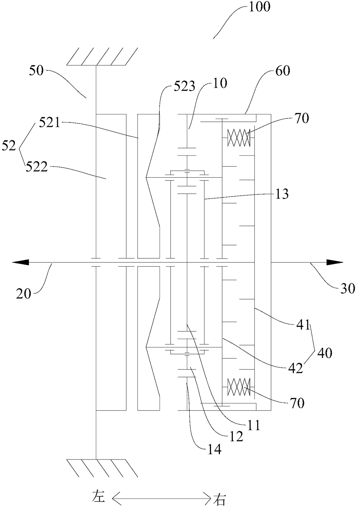
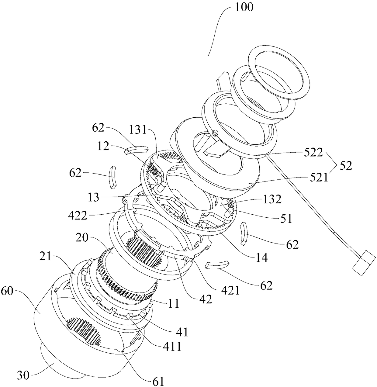
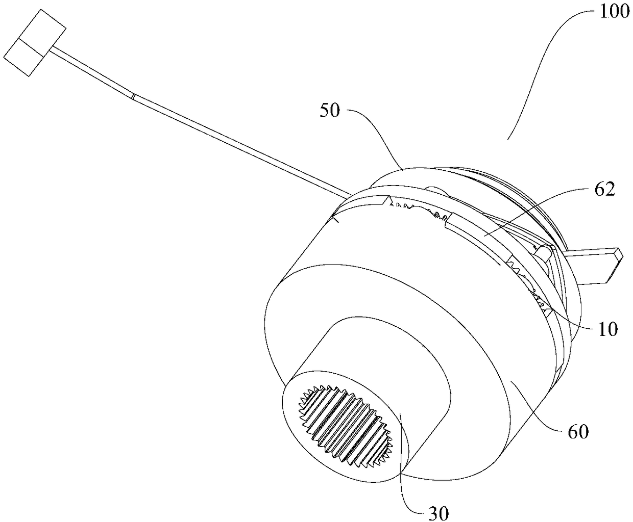
[0062] The drive shaft locking device 100 according to the embodiment of the present invention will be described in detail below with reference to the accompanying drawings. The drive shaft locking device 100 can be applied to vehicles, especially for new energy vehicles using distributed drive. The drive shaft locking device 100 It can be used to lock two drive shafts, so that the left and right wheels can rotate synchronously, which can greatly improve the ability of the vehicle to get out of trouble. The vehicle can be an electric vehicle, but not limited thereto.

[0063] Such as figure 1 and figure 2 As shown, the drive shaft locking device 100 according ...


PUM


Abstract

The invention discloses a driving shaft locking device, a power-driven system and a vehicle. The driving shaft locking device comprises a planetary gear mechanism, a first driving shaft, a second driving shaft and a power joint device and further comprises a joint part driving device, the power joint device comprises a first joint part and a second joint part, the first driving shaft is connectedto a sun wheel and is further configured to synchronously rotate with the first joint part, the second driving shaft is connected to a gear ring and is further configured to synchronously rotate withthe second joint part, the joint part driving device comprises a driving pin and a driving part, the driving pin can rotate along with the center axis of the sun wheel along with a planet carrier andcan move axially, and the driving part is used for driving the driving pin to drive the second joint part to move in the direction close to the first joint part in the axial direction so as to enablethe second joint part to be connected to the first joint part. According to the driving shaft locking device, the two driving shafts can be locked, and the escape capability of the vehicle can be improved.

Description

technical field [0001] The invention relates to the technical field of vehicles, in particular to a drive shaft locking device for a vehicle, a power drive system with the drive shaft lock device, and a vehicle with the power drive system. Background technique [0002] In the related technology, the new energy vehicle adopts a distributed drive mode, and two motors drive the wheels on both sides respectively. The speed and torque of the left and right wheels can be independently adjusted by the controller, which cancels the differential, but in a In some slippery road conditions, it is still necessary to lock the left and right axle shafts to improve vehicle passability. If the traditional electric locking differential is applied to distributed drive new energy vehicles, the differential function of the differential will be wasted, and the traditional electric locking differential has a complex structure and many parts. Take up more space. Contents of the invention [00...

Claims


Application Information

Patent Timeline
Patent Type & Authority Applications(China)
IPC IPC(8): F16H1/32F16H57/08F16H57/10B60K17/04
CPCB60K17/04F16H1/32F16H57/082F16H57/10F16H2001/327F16H2057/087F16H2200/0021F16H2200/2035B60K17/02B62D11/04F16H48/34F16H57/08
Inventor 凌和平翟震黄长安罗永孟
Owner BYD CO LTD
Why Eureka
Try Eureka