Slag cooling system for reducing amount of boiler circulating ash and working method

A technology of circulating ash and cold slag, applied in the field of cold slag system, can solve the problems of complex mechanical system structure, poor sealing effect, easy leakage of circulating water, etc., and achieve the effect of high heat transfer efficiency, reasonable structure and stable heat transfer efficiency

Inactive Publication Date: 2018-07-03
HARBIN SHUNZHI TECH CO LTD
View PDF0 Cites 2 Cited by
  • Summary
  • Abstract
  • Description
  • Claims
  • Application Information

AI Technical Summary

Problems solved by technology

The main advantages of these slag removers are: easy to meet the space layout, can be produced as a product alone, and some have a longer service life
The disadvantages are: a large amount of cooling water and a separate circulating water system are required, the sealing effect is poor, the circulating water is easy to leak, and a certain amount of extra power consumption is required. At the same time, the mechanical system structure of its operation is more complicated and the failure rate is higher.
Since the failure of the slag cooler can easily cause the shutdown of the boiler, it has not been widely used

Method used


Image

  • Slag cooling system for reducing amount of boiler circulating ash and working method

Examples


Embodiment 1

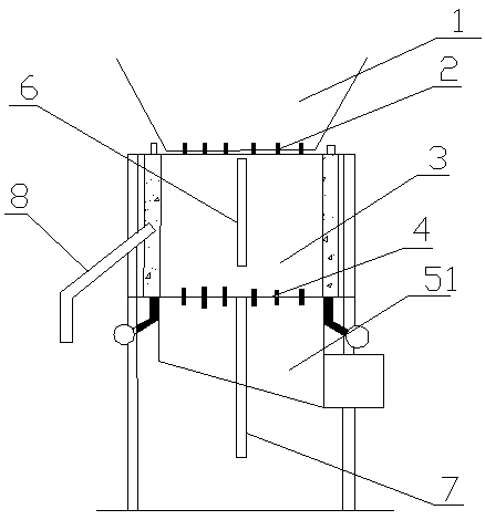
[0018] A slag cooling system for reducing boiler circulating ash, which consists of: a combustion chamber 1, a cooling chamber 3, and an air chamber 5, the combustion chamber is connected to the cooling chamber, and the cooling chamber is connected to the Air chamber connection.

Embodiment 2

[0020] 2. According to the cooling slag system for reducing boiler circulating ash amount described in Embodiment 1, the combustion chamber air distribution plate 2 is installed inside the combustion chamber, the hot slag pipe 6 is installed inside the cooling chamber, and the cooling chamber air distribution plate 2 is installed inside the combustion chamber. plate 4, an overflow port 8 is installed outside the cooling chamber, and a cold slag pipe 7 is installed in the air chamber.

Embodiment 3

[0022] According to the slag cooling system for reducing boiler circulating ash amount described in embodiment 1 or 2, the surrounding cooling chamber is composed of water-cooled wall heating surfaces, and the overflow port is connected with the water-cooled wall.


PUM


Abstract

The invention relates to a slag cooling system for reducing the amount of boiler circulating ash and a working method. The main cooling manner of existing slag coolers is a water cooling manner, and the structural forms of the existing slag coolers roughly include a packing auger type water-cooling slag removing machine, an external water-cooling sleeve rotation type water-cooling slag removing machine, an automatic slag-falling staggering type water-cooling slag removing machine and the like. The slag removing machines have the main advantages that the slag removing machines can easily meet the spatial arrangement requirements and can be independently used for producing products, and certain slag removing machines have long service lives. The slag removing machines have the disadvantagesthat a large number of cooling water and independent water circulating systems are required, the sealing effects are poor, circulating water is easily leaked, certain extra power consumption is required, meanwhile, mechanical systems are relatively complex during operation, and fault rates are relatively high. Boilers are easily shut down due to the faults of the slag coolers, so that the slag coolers are not widely used. The slag cooling system comprises a combustion chamber (1), a cooling chamber (3) and an air chamber (5), wherein the combustion chamber is connected with the cooling chamber, and the cooling chamber is connected with the air chamber. The slag cooling system is applied to the cooling of ash slag and reutilization of waste heat of boilers.

Description

Technical field: [0001] The invention relates to a cooling slag system and a working method for reducing boiler circulating ash volume, which effectively utilizes the waste heat in the boiler slag, can better save energy on the one hand, and at the same time, the cold slag form does not destroy the activity of the ash itself, and also It can reduce the carbon content in the ash and is beneficial to the comprehensive utilization of the ash. It is an ideal form of cold slag. Background technique: [0002] With the development of the times, people pay more and more attention to energy utilization and environmental protection issues. As far as the power generation industry is concerned, thermal power generation is still the main source of electricity in the world today. Therefore, boilers, as the main tool for energy conversion, are widely used in the power generation industry, and the main fuel used by boilers is coal. [0003] The temperature of slag discharged from circulati...

Claims


Application Information

Patent Timeline
Patent Type & Authority Applications(China)
IPC IPC(8): F23C10/24
CPCF23C10/24F23C2206/10
Inventor 崔志彬吴波
Owner HARBIN SHUNZHI TECH CO LTD
Why Eureka
Try Eureka