A Parameter Design Method of Fiber Bragg Grating Vibration Sensor
A vibration sensor, fiber grating technology, applied in instruments, measuring devices, using wave/particle radiation, etc., can solve the problems of time-consuming and expensive, not necessarily satisfactory results, low sensor sensitivity, etc., to improve the amplitude-frequency characteristics, The effect of high vibration frequency and high sensitivity
- Summary
- Abstract
- Description
- Claims
- Application Information
AI Technical Summary
Problems solved by technology
Method used
Image
Examples
Embodiment 1
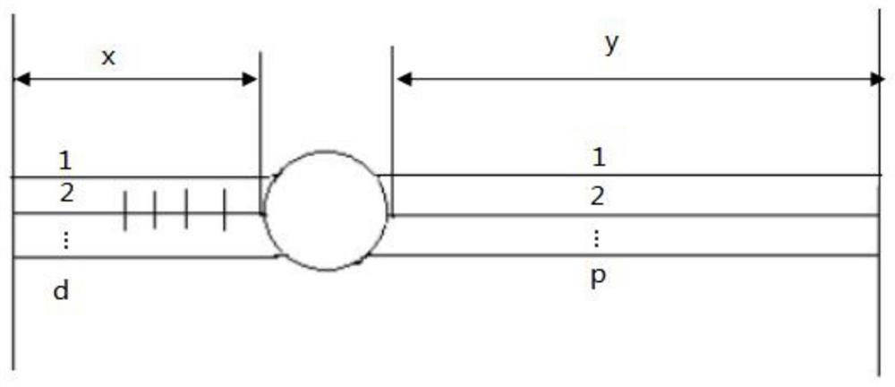
[0027] A parameter design method of a fiber grating vibration sensor, the fiber grating vibration sensor includes a substrate, an optical fiber, and a vibrator, grooves are provided on both sides of the substrate; the optical fiber includes an optical fiber and a bare fiber engraved with a grating; the The groove is on a straight line with the center of the vibrator; the optical fiber passes through the center of the vibrator and is tightly fixed in the grooves on both sides of the base; the vibrator is fixedly connected to the base through a damping sheet, Vibrate the fiber in the axial direction, such as figure 1 shown, including the following steps:
[0028] S1, setting the natural frequency f of the fiber grating vibration sensor n = 1500Hz;
[0029] S2. Select the type of optical fiber as G652 single-mode optical fiber, and obtain the Young's modulus of the optical fiber E=7.0·10 10 N / m 2 And fiber cross-sectional area S=1.23×10 -8 m 2 ;
[0030] S3. Adjust the num...
Embodiment 2
[0121] Embodiment 1 is to set other parameters by setting the natural frequency of the fiber grating vibration sensor, so as to produce the required sensor. This embodiment is to set the sensitivity of the fiber grating vibration sensor to set other parameters, thereby preparing required sensors.
[0122] Specifically, a parameter design method of a fiber grating vibration sensor, the fiber grating vibration sensor includes a substrate, an optical fiber, and a vibrator, grooves are provided on both sides of the substrate; the optical fiber includes an optical fiber engraved with a grating and a bare fiber ; the groove and the center of the vibrator are on a straight line; the optical fiber passes through the center of the vibrator and is tightly fixed in the grooves on both sides of the base; the vibrator and the base pass through a damping sheet The connection is fixed so that the optical fiber vibrates in the axial direction, comprising the following steps:
[0123] A1. Set...
Embodiment 3
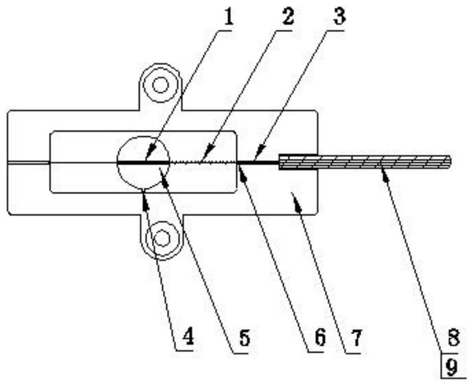
[0136] According to the parameter design method of the fiber grating vibration sensor described in embodiment 1, as figure 2 As shown, a corresponding fiber grating sensor has been made, including a base body 7, an optical fiber 2, and a mass block 5, grooves 6 are provided on both sides of the base body 7, and the optical fiber includes an optical fiber and a bare fiber engraved with a grating; The groove 6 is on a straight line with the center 1 of the mass block 5, and the optical fiber 2 passes through the center 1 of the mass block 5 and is tightly fixed in the grooves on both sides of the base body 7. The mass block 5 is fixedly connected with the base 7 through the damping plate 4, so that the optical fiber 2 vibrates in the axial direction; it also includes a protective sleeve 8 and a spiral protective tube 9, and the optical fiber passing through the groove on one side of the base 7 passes through Through the protective sleeve 8 , the spiral protective tube 9 covers ...
PUM
 Abstract
Description
Claims
Application Information
 - R&D
- Intellectual Property
- Life Sciences
- Materials
- Tech Scout
- Unparalleled Data Quality
- Higher Quality Content
- 60% Fewer Hallucinations
Browse by: Latest US Patents, China's latest patents, Technical Efficacy Thesaurus, Application Domain, Technology Topic, Popular Technical Reports.
© 2025 PatSnap. All rights reserved.Legal|Privacy policy|Modern Slavery Act Transparency Statement|Sitemap|About US| Contact US: help@patsnap.com


