Fixation member
A technology for fixing parts and release layers, applied in electronic equipment, applications, coatings, etc., can solve the problems of reduced friction coefficient, increased surface roughness, inability to obtain high gripping force, etc., and achieves low electrification, high The effect of friction and high releasability
- Summary
- Abstract
- Description
- Claims
- Application Information
AI Technical Summary
Problems solved by technology
Method used
Image
Examples
Embodiment approach 1
[0029] (pressure roller)
[0030] The fixing member in this embodiment is suitable for use in a fixing unit (fixing device) of an image forming apparatus such as an electrophotographic copier and a printer. Thereby, the unfixed toner image can be fixed on a recording medium such as paper by heat and pressure. In this embodiment, a pressure roller is exemplified as a fixing member.
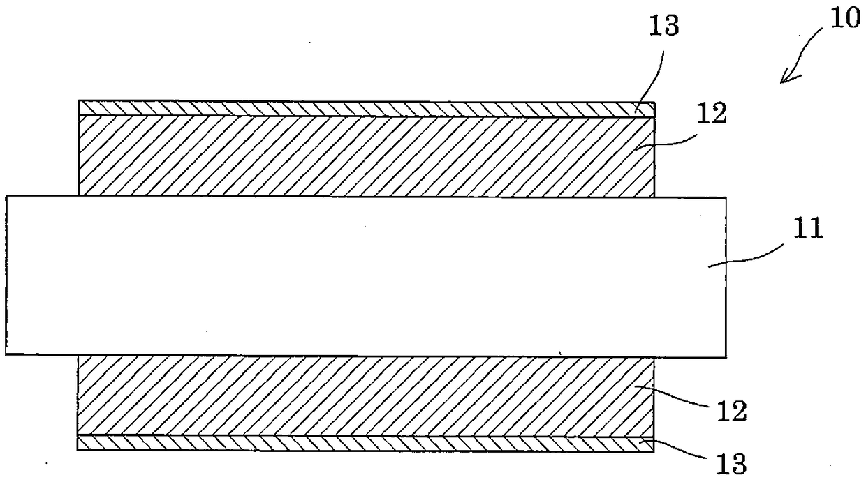
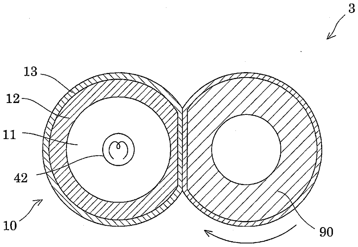
[0031] figure 1 is a cross-sectional view in the circumferential direction showing a configuration example of the fixing member according to Embodiment 1, figure 2 It is an axial cross-sectional view showing a configuration example of the fixing member according to the first embodiment. As shown in the figure, the pressure roller 10 as a fixing member includes a core body 11, an elastic layer 12 formed on the outer peripheral surface of the core body 11, and a release layer 13 formed on the outer peripheral surface of the elastic layer 12, which are stacked in this order from the inner side. T...
Embodiment approach 2
[0059] (fixing unit)
[0060] Next, the fixing device according to this embodiment will be described. The fixing device according to the second embodiment includes the pressure roller 10 according to the first embodiment, which is mounted on the image forming device. In addition, the same code|symbol is attached|subjected to the same member as Embodiment 1, and repeated description is abbreviate|omitted.
[0061] image 3 It is a cross-sectional view showing a configuration example of the fixing device according to the second embodiment. Such as image 3 As shown, the fixing device 1 includes: a pressure roller 10, a fixing belt 20 disposed opposite to the pressure roller 10, and at a position opposite to the pressure roller 10, the fixing belt 20 is pressed against the pressure roller 10 from the inside to form a predetermined shape. The pressing member 30 of the nip portion, and the heating means 40 for heating the fixing belt 20 to a predetermined temperature. It shoul...
Embodiment approach 3
[0067] (fixing unit)
[0068] Next, the fixing device according to this embodiment will be described. The fixing device according to the third embodiment includes the pressure roller 10 according to the first embodiment, is mounted on the image forming apparatus, and has a configuration different from that of the fixing device 1 according to the second embodiment. In addition, the same code|symbol is attached|subjected to the same component as Embodiment 2, and repeated description is abbreviate|omitted.
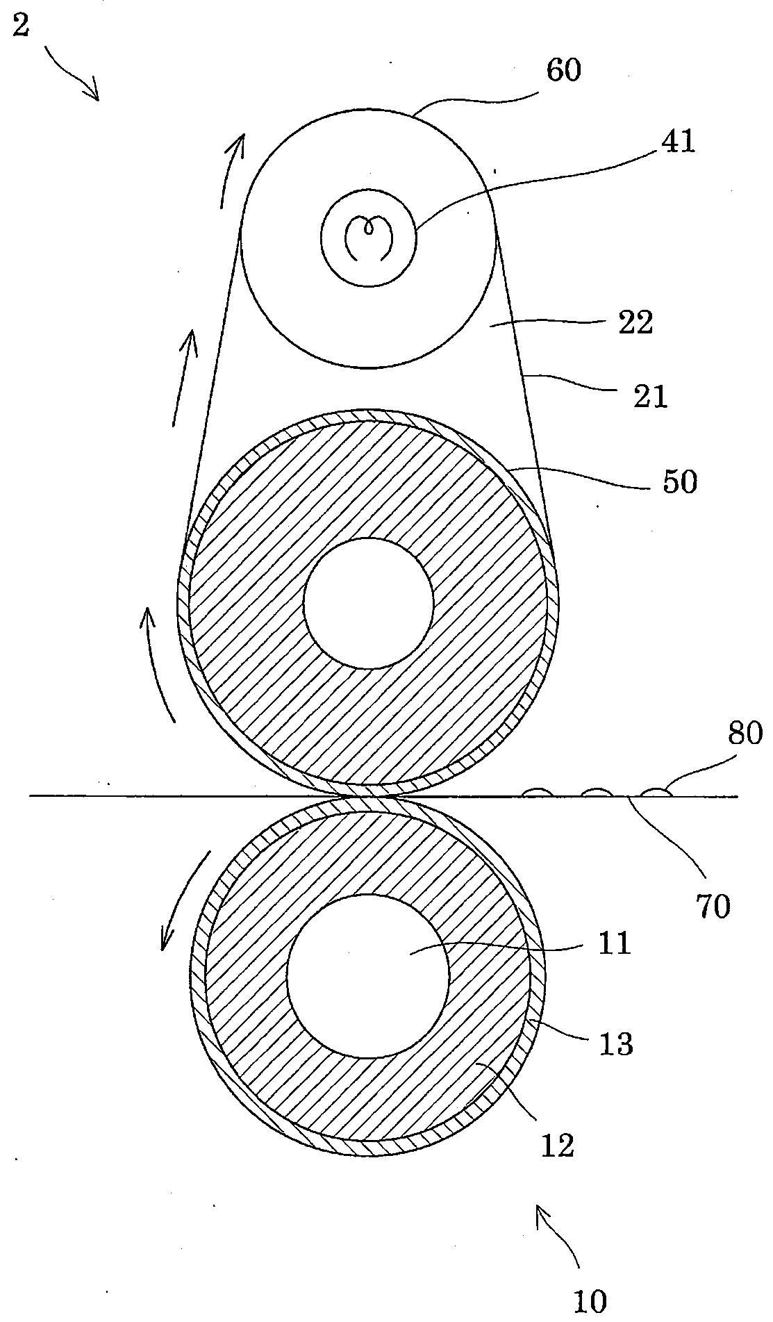
[0069] Figure 4 It is a cross-sectional view showing a configuration example of a fixing device according to Embodiment 3. Such as Figure 4 As shown, the fixing device 2 includes: a pressure roller 10 , a fixing belt 21 disposed opposite to the pressure roller 10 , an inner roller 50 that presses the fixing belt 21 against the pressure roller 10 from the inside, and a heating roller with a built-in heating means 41 . 60. An inner roller 50 and a heating roller 60 are ...
PUM
| Property | Measurement | Unit |
|---|---|---|
| surface roughness | aaaaa | aaaaa |
| melting point | aaaaa | aaaaa |
| thickness | aaaaa | aaaaa |
Abstract
Description
Claims
Application Information
 - R&D
- Intellectual Property
- Life Sciences
- Materials
- Tech Scout
- Unparalleled Data Quality
- Higher Quality Content
- 60% Fewer Hallucinations
Browse by: Latest US Patents, China's latest patents, Technical Efficacy Thesaurus, Application Domain, Technology Topic, Popular Technical Reports.
© 2025 PatSnap. All rights reserved.Legal|Privacy policy|Modern Slavery Act Transparency Statement|Sitemap|About US| Contact US: help@patsnap.com


