

Gear forming device and gear manufacturing method
A molding device and manufacturing method technology, applied in the field of net-shaping molding devices, can solve the problems of limited cavity space and forging load, low material yield, low production efficiency, etc., to achieve reduced loss, high material yield, The effect of increasing production rate
- Summary
- Abstract
- Description
- Claims
- Application Information
AI Technical Summary
Problems solved by technology
Method used
Image

Examples
Embodiment Construction
[0018] The present invention will be described in detail below in conjunction with the accompanying drawings and embodiments.
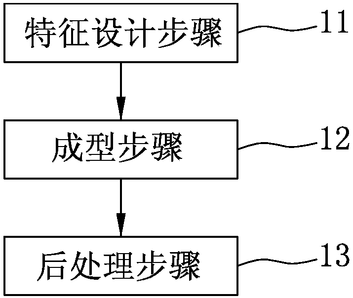
[0019] refer to figure 1 And FIG. 2 , an embodiment of the manufacturing method of the gear of the present invention includes a feature design step 11 , a forming step 12 , and a post-processing step 13 . The manufacturing method is matched with a molding device 2 .
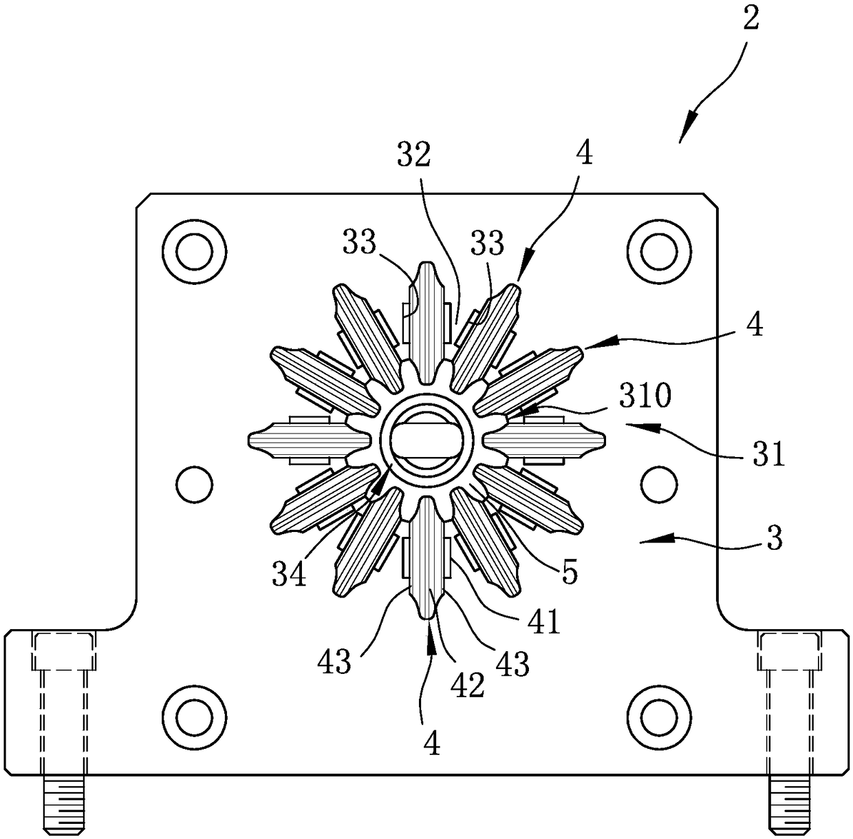
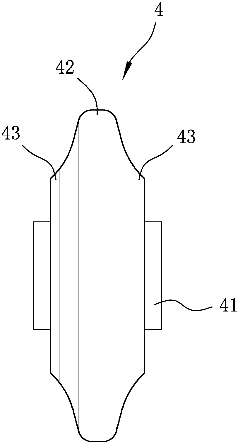
[0020] refer to figure 2 , image 3 and Figure 4 , the forming device 2 includes a base 3 and several rollers 4 pivotally mounted on the base 3 . The base 3 includes a body portion 31 surrounding a space 310 , and a plurality of spacers 32 arranged at equiangular intervals and disposed in the space 310 . The spacer 32 divides the space 310 into a plurality of accommodating grooves 33 arranged at equiangular intervals, and a through groove 34 communicating with the accommodating grooves 33 . The rollers 4 are respectively pivotally disposed in the receiving grooves 33 of the base ...
PUM
 Abstract
Description
Claims
Application Information