Burner for synthesizing glass particles and method for producing porous glass body

a technology of synthesizing glass particles and burners, which is applied in the direction of glass deposition burners, combustion types, and lump and pulverizing fuel, etc. it can solve the problems of comparatively low raw material yield, insufficient hydrolytic reaction or oxidation reaction efficiency of raw materials to glass particles, and inability to say other things, to achieve the effect of enhancing the reaction efficiency of raw materials to glass and efficiently producing glass particles

Inactive Publication Date: 2006-12-05
SUMITOMO ELECTRIC IND LTD
View PDF10 Cites 0 Cited by
  • Summary
  • Abstract
  • Description
  • Claims
  • Application Information

AI Technical Summary

Benefits of technology

[0036]To produce glass particles efficiently, it is preferable that gas arrangement is made so that raw material gas is placed at the center, and combustible gas exists at one and the same place as or at a closest place to the raw material gas (to raise the temperature of the reaction area) while oxygen gas is supplied to the reaction area from the surroundings. Particularly, in this arrangement form, oxygen gas is jetted from a comparatively narrow area. The oxygen gas is diffused and fed to the center portion efficiently if the following two conditions with respect to the structure of the jet port of the oxygen gas are satisfied. That is, the outer wall surface of the oxygen gas jet port should be more protruding than the inner wall surface thereof by the protruding length which is 30 or more times as large as the gap width of the inner wall surface. In addition, the flow rate of the oxygen gas should be 1.2 or more times as high as the average flow rate of gases inner than the oxygen gas. Thus, there is an effect that the oxidation reaction and the hydrolytic reaction of the raw material are accelerated in the center portion so that the reaction efficiency from the raw material to glass is enhanced remarkably. The structure of the burner satisfying such conditions, and the reaction conditions are essential for the present invention.

Problems solved by technology

Therefore, it cannot be also said that the efficiency of the hydrolytic reaction or the oxidation reaction from the raw material to the glass particles is sufficiently high.
Thus, there is a problem that the raw material yield (the ratio of the produced quantity of the porous glass body to the input quantity of the raw material) is comparatively low.
However, in the multi-nozzle burner, a large number of small-diameter nozzles have to be disposed in a limited area of the burner.
Thus, it takes a lot of trouble to manufacture the multi-nozzle burner in comparison with the concentric multi-tubular burner.
In addition, the positions and directions of the nozzles affect the reaction extremely delicately, so that the raw material yield varies largely due to a slight displacement in the burner structure (nozzle layout or the like).
Thus, there is a problem that it is difficult to obtain a stable burner performance and hence a stable porous glass body producing capacity.
On the contrary, there is a problem that the form of the nozzles largely affects the efficiency of deposition of the porous glass (there is a large individual difference among burners).
In fact, it takes a lot of trouble to manufacture a large number of nozzles.
However, a problem inheres in the concentric multi-tubular burner so that the efficiency of mixture among raw material gas, combustion-support gas and combustible gas is not as high as that conducted in the multi-nozzle burner.
As a result of investigation of this reason, it was proved that the oxygen quantity diffusing to the center portion of the raw material was not always sufficient (in an oxygen diffusion rate-determining process).
However, it was proved that if the supply oxygen quantity was increased, the temperature of the flames fell so that the efficiency of reaction of the raw material also dropped.
It was therefore proved that simple increase in oxygen quantity could not solve the problem.

Method used


Image

  • Burner for synthesizing glass particles and method for producing porous glass body
  • Burner for synthesizing glass particles and method for producing porous glass body
  • Burner for synthesizing glass particles and method for producing porous glass body

Examples


examples 1 to 6

, AND COMPARATIVE EXAMPLES 1 TO 4

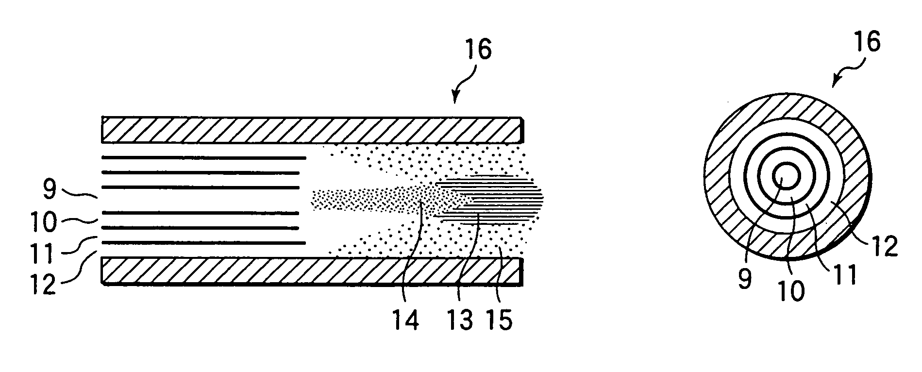
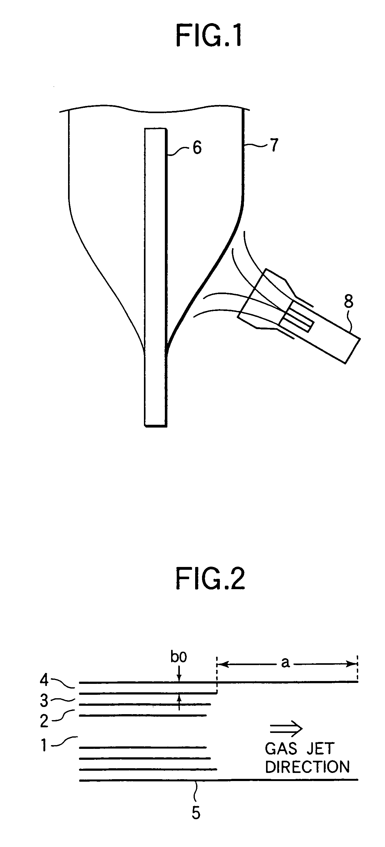
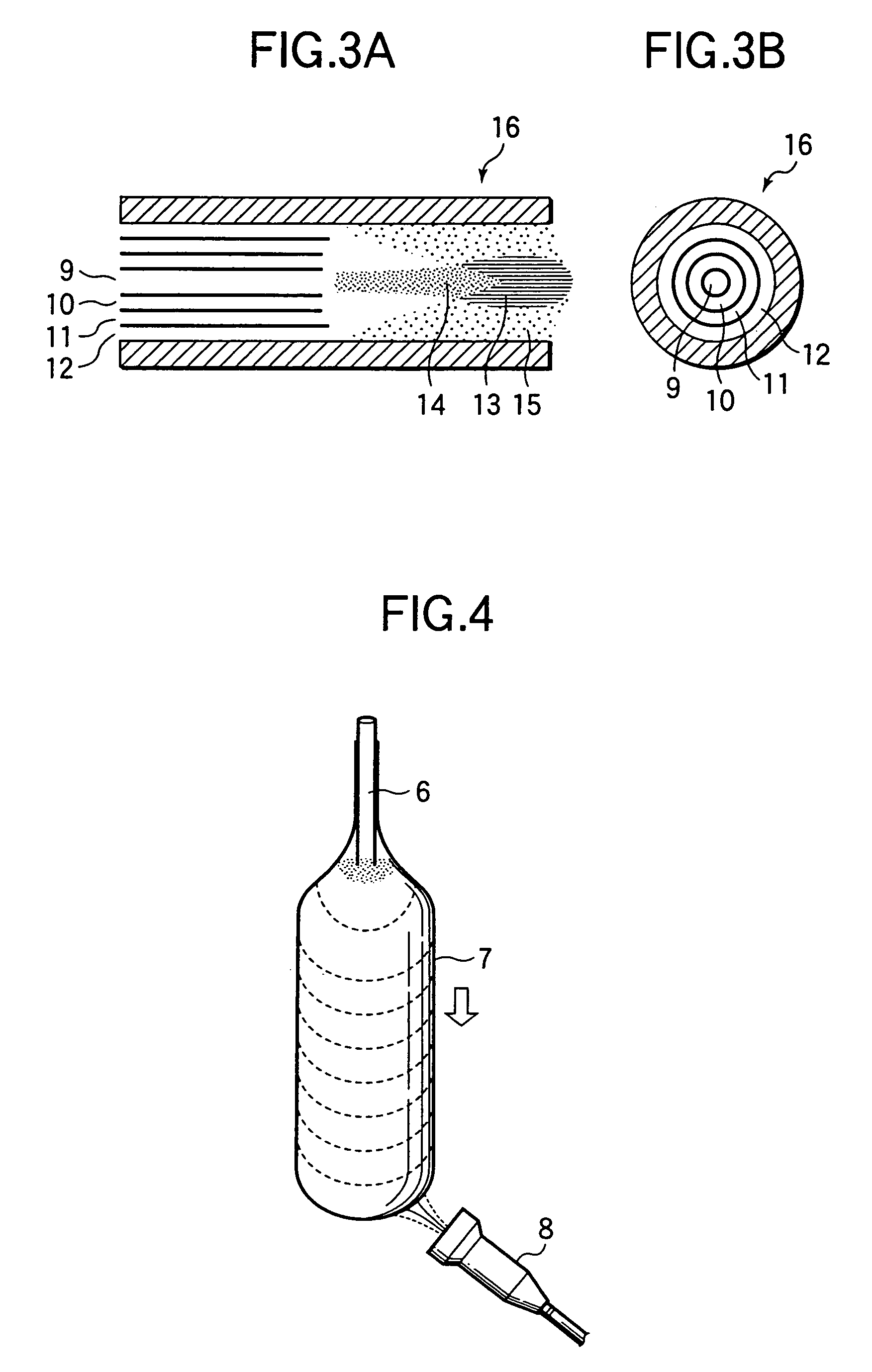
[0042]As shown in FIG. 1, glass particles were synthesized by use of a burner 8 for synthesizing glass particles according to the structure of the present invention, and a porous glass body was produced by a VAD method for depositing glass particles 7 around a starting rod 6.

[0043]The burner 8 used was a concentric 16-tubular burner. A center port group 5 of the burner 8 was constituted by a first port 1 for jetting raw material gas (SiCl4) and hydrogen gas, a second port 2 for jetting hydrogen gas, a third port 3 for jetting Ar gas which was seal gas, and a fourth port 4 (corresponding to the first oxygen gas jet port in the present invention) for jetting oxygen gas, as shown in its side view of FIG. 2. Outside this center port group 5, there were provided an outside port group with three groups for forming flames in combination of (Ar / H2 / Ar / O2).

[0044]In the burner 8, as the fourth port 4 which was the first oxygen gas jet port, there were used a st...


PUM

PropertyMeasurementUnit
timeaaaaaaaaaa
outer diameteraaaaaaaaaa

Abstract

A concentric multi-tubular burner for synthesizing glass particles having a center port group constituted by a combination of jet ports of raw material gas, combustible gas and oxygen gas, wherein an outer wall of the oxygen gas jet port in the center port group protrudes more toward a burner head than an inner wall of the oxygen gas jet port. The flow rate of oxygen gas jetted from the oxygen gas jet port of the center port group is controlled to be in a proper range.

Description

[0001]This application is a divisional of application Ser. No. 09 / 952,502 filed 14 Sep., 2001, now U.S. Pat. No. 6,725,690.BACKGROUND OF THE INVENTION[0002]1. Field of the Invention[0003]The present invention relates to a burner for synthesizing glass particles and a method for producing porous glass body in order to manufacture glass articles by a vapor phase synthesis method.[0004]2. Description of the Related Art[0005]As a method for obtaining a porous glass body which is a precursor for manufacturing various glass articles such as optical fibers, photo-mask materials, quartz glass, etc., there is generally used a vapor phase synthesis method such as a VAD (Vapor Phase Axial Deposition) method, an OVD (Outside Vapor Deposition) method, or the like. In such a method, raw material gas (SiCl4 or the like), combustible gas (hydrogen, methane, propane, or the like), and combustion-support gas (oxygen, or the like) are jetted from a plurality of different ports and mixed with one anoth...

Claims


Application Information

Patent Timeline
Patent Type & Authority Patents(United States)
IPC IPC(8): C03B19/06C03B8/04C03B19/10C03B19/14C03B37/014C03B37/018
CPCC03B19/106C03B19/1423C03B37/0142C03B2207/06C03B2207/08C03B2207/20C03B2207/22C03B2207/36C03B2207/40C03B2207/42Y02P40/57C03B37/018
Inventor ENOMOTO, TADASHIOHGA, YUICHIAKAIKE, NOBUYAAIKAWA, HARUHIKOMATSUO, TAKASHINAKAMURA, MOTONORI
Owner SUMITOMO ELECTRIC IND LTD
Why Eureka
Try Eureka