Miniature clutch structure and manipulator provided with same

A manipulator and manipulator technology, applied in the field of manipulators, can solve the problems of inability to achieve effective envelope grasping, limited application range of manipulators, lack of under-actuating capability, etc., and achieve the effects of small loss, simple structure and small volume.

Pending Publication Date: 2018-07-06
SUZHOU JODELL ROBOTICS CO LTD
View PDF0 Cites 4 Cited by
  • Summary
  • Abstract
  • Description
  • Claims
  • Application Information

AI Technical Summary

Problems solved by technology

At present, dexterous manipulators capable of performing complex functions at home and abroad are mostly used in scientific research and national defense fields due to their high prices, which limits the application range of manipulators.
Some domestic units are also developing more practical three-finger dexterous hands, such as the three-finger bionic manipulator of the Institute of Automation, Chinese Academy of Sciences. The simplified design of the mechanism reduces the cost, but the biggest problem is that this type of finger does not have under-actuation capability, that is, the end of the finger can only move according to a fixed trajectory. When the proximal end of the finger receives resistance, the end of the finger stops. Movement, unable to achieve effective envelope capture of the target
[0003] In addition, in order to make the mechanical fingers have under-actuation capability, a clutch structure with small volume and strong clutch effect is required, but the current under-actuation structures are relatively large in size, and it is difficult to apply them to the manipulator.

Method used


Image

  • Miniature clutch structure and manipulator provided with same
  • Miniature clutch structure and manipulator provided with same
  • Miniature clutch structure and manipulator provided with same

Examples


Embodiment 1

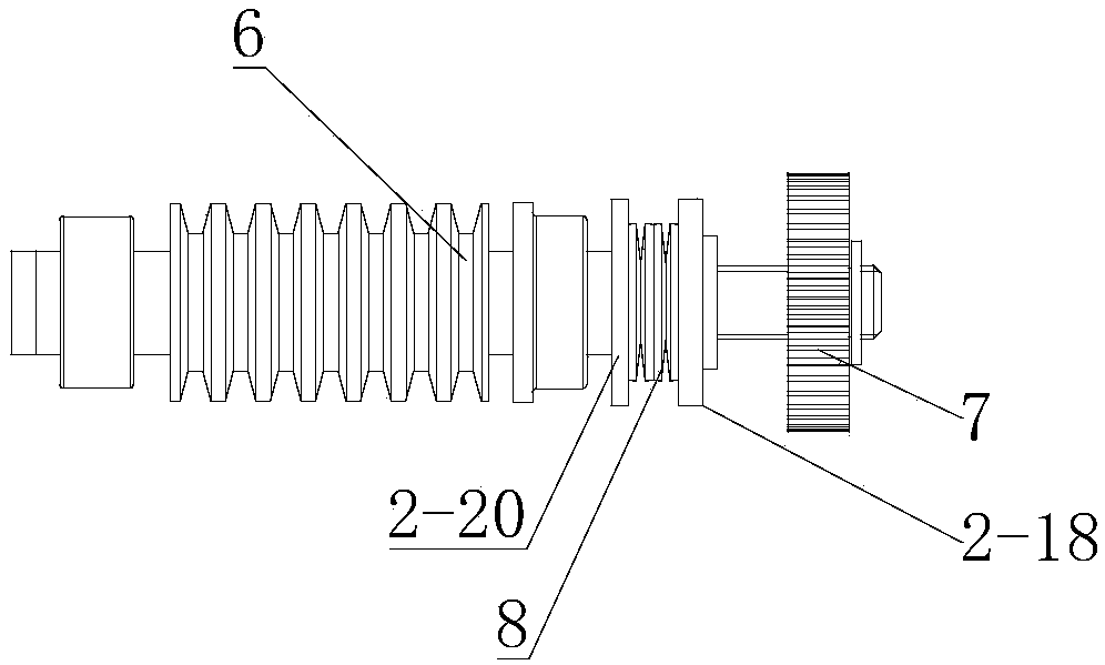
[0064] Such as figure 1 Shown, it is; Wherein, described miniature clutch structure comprises:

[0065] The first threaded connector 6 has external threads;

[0066] The second threaded connector 7 has an internal thread and is in a threaded state with the first threaded connector;

[0067] The spring 8 has one end abutting against the first threaded connection and the other end abutting against the second threaded connection; and the spring is in a compressed state.

[0068] In this way, the spring in the compressed state will give a certain moment to the abutting first threaded connection and the second threaded connection (the first threaded connection and the second threaded connection compress the spring to a certain extent by abutting against it) , so that the first threaded connection and the second threaded connection are difficult to separate by screwing (screwing is essentially the frictional movement of the threaded surfaces in contact with each other, in the firs...

Embodiment 2

[0071] Like the micro-clutch structure described above, the difference in this embodiment is that the first threaded connecting piece is a threaded rod with an abutment portion arranged thereon, the second threaded connecting piece is a threaded cap, and the The spring is sheathed on the threaded rod, with one end abutting against the abutting portion and the other end abutting against the side of the threaded cap.

[0072] In this way, the threaded cap is fixed on the threaded rod by screwing the thread; the threaded rod can be driven to rotate by rotating the threaded cap, and after the threaded rod is subjected to a certain resistance, the driving of the threaded cap is separated; it is simple and convenient; The combination of pair and spring can make it generate a large driving torque. In this way, a clutch structure with a large driving torque can be generated through a micro-thread pair and a spring, thereby increasing the scope of application of the clutch structure. Fo...

Embodiment 3

[0075] Like the micro-clutch structure described above, the difference in this embodiment is that the first threaded connection is a threaded rod, the second threaded connection is a hollow threaded column, and the spring is sleeved on the On the threaded post; the threaded rod is provided with an abutting portion, and the threaded post is provided with an abutting projection, one end of the spring abuts against the abutting portion, and the other end abuts against the abutting projection rise.

[0076] In this way, the threads of the threaded rod and the threaded column have more contact, and their threads are less likely to be damaged, thereby increasing their service life.


PUM


Abstract

The invention discloses a miniature clutch structure and a manipulator provided with the same. The miniature clutch structure comprises a first threaded connecting piece provided with an outer thread,a second threaded connecting piece provided with an inner thread, and a spring, wherein the second threaded connecting piece and the first threaded connecting piece are located in a threaded connection state; one end of the spring abuts against the first threaded connecting piece, the other end of the spring abuts against the second threaded connecting piece and is connected with the second threaded connecting piece; the spring is in a compressed state; and the manipulator comprises the miniature clutch structure. The clutch effect is realized through a thread pair form, the structure is simple, loss is small, machining is convenient, and the service life is long; the size is small, and the provided clutch effect is high; and when an object is grasped, the simple and convenient effects are achieved, and adaptability is high.

Description

technical field [0001] The invention relates to the technical field of manipulators, in particular to a miniature clutch structure and a manipulator with the clutch structure. Background technique [0002] As the executive part of the manipulator system and the external operation object, the function and performance of the manipulator directly affect or even determine the performance of the entire robot system. With the rise of my country's robotic arm industry, especially after the rapid promotion and application of collaborative robots represented by UR, the demand for dexterous manipulators that can perform complex functions will increase. At present, dexterous manipulators capable of performing complex functions at home and abroad are mostly used in scientific research and national defense fields due to their high prices, which limits the application range of manipulators. Some domestic units are also developing more practical three-finger dexterous hands, such as the t...

Claims


Application Information

Patent Timeline
Patent Type & Authority Applications(China)
IPC IPC(8): B25J9/10B25J15/02B25J15/10
CPCB25J9/102B25J9/104B25J15/0233B25J15/10
Inventor 于永舵
Owner SUZHOU JODELL ROBOTICS CO LTD
Why Eureka
Try Eureka