Steel pipe restraining concrete joint structure, corresponding truss structure and construction method

A technology for constraining concrete and node structures, applied in building construction, erection/assembly of bridges, bridge parts, etc., can solve the problems of node failure, easy cracking, fatigue cracks, loss of bearing capacity of truss structures, etc. Reliable mechanical properties and the effect of increasing plasticity

Pending Publication Date: 2018-07-06
FUZHOU UNIV
View PDF11 Cites 5 Cited by
  • Summary
  • Abstract
  • Description
  • Claims
  • Application Information

AI Technical Summary

Problems solved by technology

Under daily fatigue loads, the joints of concrete-filled steel tube trusses are prone to cracking. Fatigue cracks originate from the initial defects in the high-stress area. Near the "hot spot", the surface cracks propagate and penetrate the pipe wall, and gradually expand to destroy the joints, resulting in the failure of the entire truss. loss of structural capacity

Method used


Image

  • Steel pipe restraining concrete joint structure, corresponding truss structure and construction method
  • Steel pipe restraining concrete joint structure, corresponding truss structure and construction method
  • Steel pipe restraining concrete joint structure, corresponding truss structure and construction method

Examples


Embodiment Construction

[0022] In order to make the above-mentioned features and advantages of the present invention more comprehensible, the following specific embodiments are described in detail with reference to the accompanying drawings.

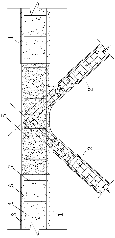
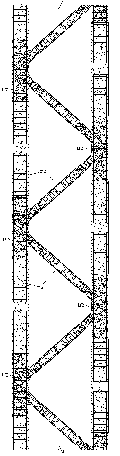
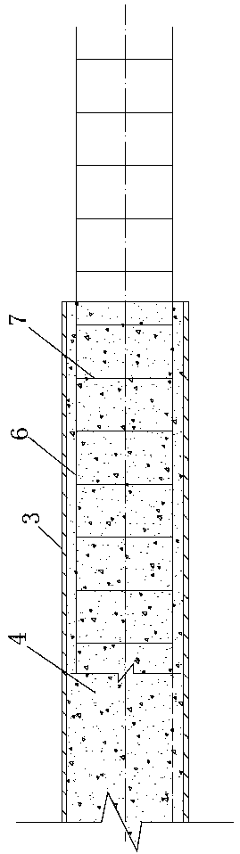
[0023] Such as Figure 1-7 As shown, a steel pipe confined concrete node structure includes a chord 1 and a web 2, and both the chord and the web include a steel pipe 3 and a steel grid frame, and one end of the steel grid frame is pre-embedded by ordinary concrete 4 Both the inside and the other end of the steel pipe extend out of the steel pipe, and the chords and webs are connected to each other through an external steel grid frame, and ultra-high performance concrete 5 is poured at the connection.

[0024] In the embodiment of the present invention, the reinforced grid includes several longitudinal bars 6, and several longitudinal bars are bound together by several stirrups 7, and the joints are encrypted with longitudinal bars and stirrups to reduce the UH...


PUM


Abstract

The invention relates to a steel pipe restraining concrete joint structure comprising chord members and web members. The chord members and the web members comprise steel pipes and reinforcement mesh frames. One ends of the reinforcement mesh frames are pre-embedded in the steel pipes through common concrete correspondingly, and the other ends of the reinforcement mesh frames all extend out of thesteel pipes. The chord members and the web members are mutually connected through the external reinforcement mesh frames, and ultrahigh-performance concrete is poured in the connecting positions of the chord members and the web members. The structure is simple, the advantages of high bearing capability and easy construction are achieved, and the defect of steel pipe fatigue caused by welding of the adjacent steel pipes in the communicating positions of steel pipe concrete truss joints is overcome.

Description

technical field [0001] The invention relates to a steel pipe restrained concrete node structure, a corresponding truss structure and a construction method. Background technique [0002] Concrete filled steel pipe refers to a component formed by filling concrete in steel pipes. Usually, steel pipes and the core concrete inside bear external loads together, which can make up for the shortcomings of steel pipes and concrete when they are used alone. Concrete-filled steel tubes are often used in long-span space structures and bridges in the form of trusses. As a concrete-filled steel tube truss system, common forms include flat or spatial K, T, X, Y, and N-type concrete-filled steel tube nodes. K-type nodes are the most common. At the nodes of the concrete-filled steel tube truss structure, on the intersecting line connecting the branch and the main pipe, due to the sudden change in geometric shape, and the existence of welding defects and welding residual tensile stress betwee...

Claims


Application Information

Patent Timeline
Patent Type & Authority Applications(China)
IPC IPC(8): E04B1/58E04G21/00E01D19/00E01D21/00E01D101/20E01D101/30
CPCE01D19/00E01D21/00E04B1/58E04G21/00E01D2101/20E01D2101/30
Inventor 韦建刚周俊黄冀卓吴庆雄
Owner FUZHOU UNIV
Why Eureka
Try Eureka