
Bent radio frequency coaxial connector

A radio frequency coaxial and connector technology, which is applied in the direction of connection, two-part connection device, and parts of the connection device, etc., can solve the problems of unreliable electrical connection, large gap between electrical connection and plugging parts, and loose connection. , to achieve the effect of improving adaptability and electricity safety, reducing the difficulty of assembly, and being convenient to use and assemble.

Pending Publication Date: 2018-07-06
江苏华吉通信科技有限公司
View PDF9 Cites 1 Cited by
  • Summary
  • Abstract
  • Description
  • Claims
  • Application Information

AI Technical Summary

Problems solved by technology

Connectors are generally composed of three basic units: shell, insulator, and contact body. However, the manufacture of curved RF coaxial connectors is more complicated than that of straight ones. The use of an integrated shell structure not only requires higher assembly space for electrical components, but also And it is difficult to apply to the installation of cables that are easy to change angles, easy to wear and deform, and affect performance, and when the height of the connection port is inconsistent, there is a loose connection, and the gap between the electrical connection and socket parts after adjustment is large, resulting in unreliable electrical connection, etc. The problem is that the surface of the contact will produce film resistance, and the film layer will undergo mechanical breakdown under high contact pressure, or electrical breakdown under high voltage and high current, which limits the practicality of the connector

Method used


Image

  • Bent radio frequency coaxial connector
  • Bent radio frequency coaxial connector
  • Bent radio frequency coaxial connector

Examples


Embodiment Construction

[0025] The specific embodiments of the present invention will be further described below in conjunction with the accompanying drawings.

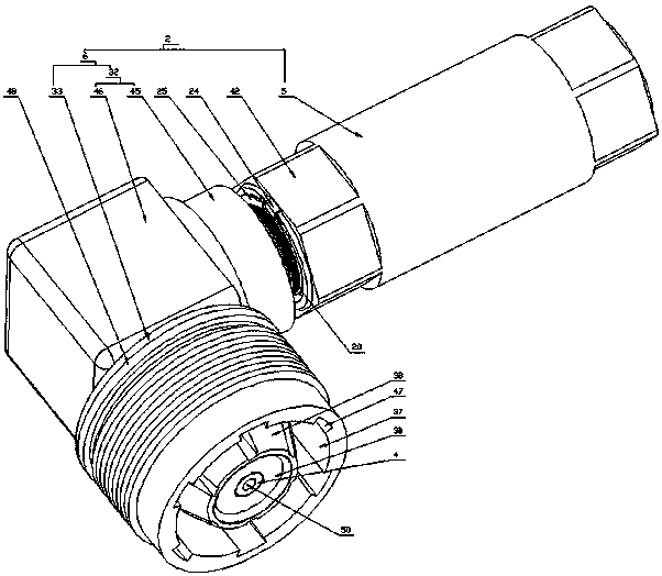
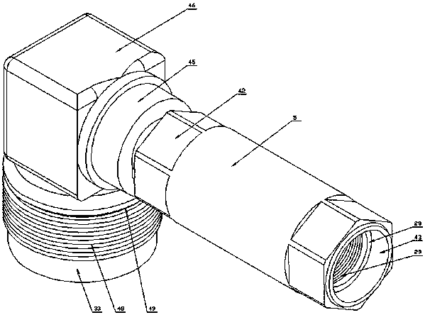
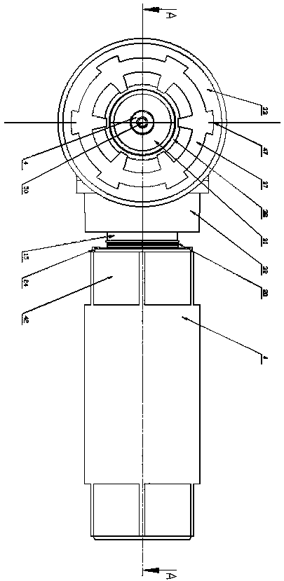
[0026] An angled radio frequency coaxial connector, comprising an inner conductor 1 and an outer shell 2, wherein the inner conductor 1 includes a first contact body 3 and a second contact body 4, and the outer shell 2 includes a first shell 5 and the second housing 6, the two ends of the first contact body 3 are respectively provided with a first jack 7 and a contact pin 8, and a wire spring 9 is provided outside the contact pin 8, and a wire spring 9 is provided on the first contact body 3. The first protruding ring 10 and the second protruding ring 11, a spacer sleeve 12 is provided between one side of the first protruding ring 10 and the second protruding ring 11, and a spacer sleeve 12 is provided between the other side and the first housing 5 respectively. The first insulating sleeve 13 and the second insulating sleeve 14, the section ...


PUM


Abstract

The invention relates to a bent radio frequency coaxial connector which comprises an inner conductor and an outer shell. The inner conductor comprises a first contact and a second contact, the outer shell comprises a first shell and a second shell, a spacing sleeve is arranged between one sides of a first convex ring and a second convex ring of the first contact, a first insulating sleeve and a second insulating sleeve are arranged between the first shell, an end sleeve is arranged between the first insulating sleeve and each of the first shell and the second shell, a clamping ring, a plurality of clamping ring ports, a retaining ring and a first limiting ring are arranged outside each end sleeve, a clamping plate is arranged in a guide sleeve of the first shell, a third insulating sleeveis arranged between the second contact and the second shell, and the second shell comprises a through connection shell and a connection shell. A connector outer shell structure which can be rotated relatively, adjusted and locked is adopted, so that the inner conductor can be limited and stably assembled; pin connection depth is adjusted, so that reliable contact is guaranteed, contact resistanceis reduced, generation of film resistance is avoided, assembly difficulty requirements are lowered, and suitability and safety of using electricity are improved.

Description

technical field [0001] The invention relates to a curved radio frequency coaxial connector, which belongs to the technical field of electrical connectors. Background technique [0002] With the rapid development of my country's electromechanical industry, the overall technical level of the industry has been greatly improved. Frequency coaxial connectors are widely used as a component attached to cables or installed on instruments, and are indispensable key components of coaxial transmission systems. . The development of miniaturization has made the space for coaxial cable assembly jumpers smaller and smaller. Using curved RF coaxial connectors instead of traditional straight coaxial connectors can reduce the bending of cable assemblies in a small space and ensure its Has good electrical properties. Connectors are generally composed of three basic units: shell, insulator, and contact body. However, the manufacture of curved RF coaxial connectors is more complicated than that...

Claims


Application Information

Patent Timeline
Patent Type & Authority Applications(China)
IPC IPC(8): H01R13/02H01R13/40H01R13/502H01R13/64H01R24/40H01R27/00
CPCH01R13/02H01R13/40H01R13/502H01R13/64H01R24/40H01R27/00
Inventor 戴礼
Owner 江苏华吉通信科技有限公司
Learn More