Energization control method and system of battery cabinet

A battery cabinet and electrical control technology, applied in the field of lithium-ion batteries, can solve the problems of long power-on time, increased maintenance costs, and low power-on efficiency, and achieve the goals of shortening power-on time, increasing hardware costs, and improving power-on efficiency Effect

Inactive Publication Date: 2018-07-06
CONTEMPORARY AMPEREX TECH CO
View PDF2 Cites 7 Cited by
  • Summary
  • Abstract
  • Description
  • Claims
  • Application Information

AI Technical Summary

Problems solved by technology

[0003] Generally, when multiple parallel battery cabinets are powered on at high voltage, the voltage of the battery cabinets is inconsistent, and when they are connected in parallel, the current is too large, so the relay cannot be closed, which may cause all the battery cabinets to fail to be powered on.
When the voltage difference of multiple battery cabinets is large, if the internal resistance of the lithium-ion battery pack in the battery cabinet is small, the current will rise instantaneously if forced to connect in parallel, which will cause damage to the circuit of the battery cabinet controller and even the entire battery cabinet control system damage to
For this reason, the existing technology generally uses PCS to charge the battery cabinets with low voltage separately, and then powers on when all the battery cabinets have the same voltage. However, this requires manual control and cannot be done automatically, which brings increased labor costs and maintenance costs. increase, and the power-on time is too long, resulting in low power-on efficiency

Method used


Image

  • Energization control method and system of battery cabinet
  • Energization control method and system of battery cabinet
  • Energization control method and system of battery cabinet

Examples


specific Embodiment 1

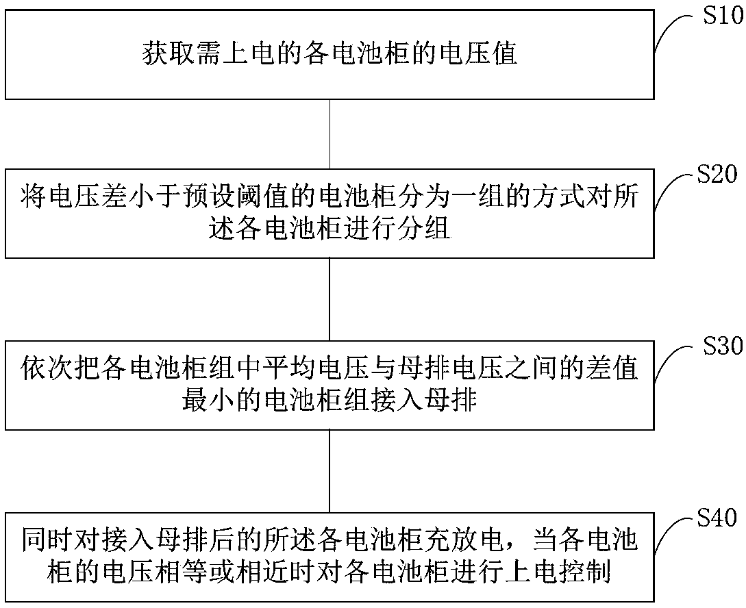
[0038] Specific embodiment 1, please refer to Figure 5 The power-on control method of the battery cabinet provided in this embodiment includes the following steps.

[0039] S11. Sort the average voltage value of each battery cabinet group that is not connected to the busbar from low to high;

[0040] S21. According to the sorting result, connect the battery cabinet group with the lowest average voltage value to the busbar for charging;

[0041] S31. When the voltage value of the busbar rises to the average voltage value of the second-lowest battery cabinet group, connect the second-highest battery cabinet group to the busbar for charging;

[0042] S41, and so on, until all battery cabinets are connected to the busbar for charging.

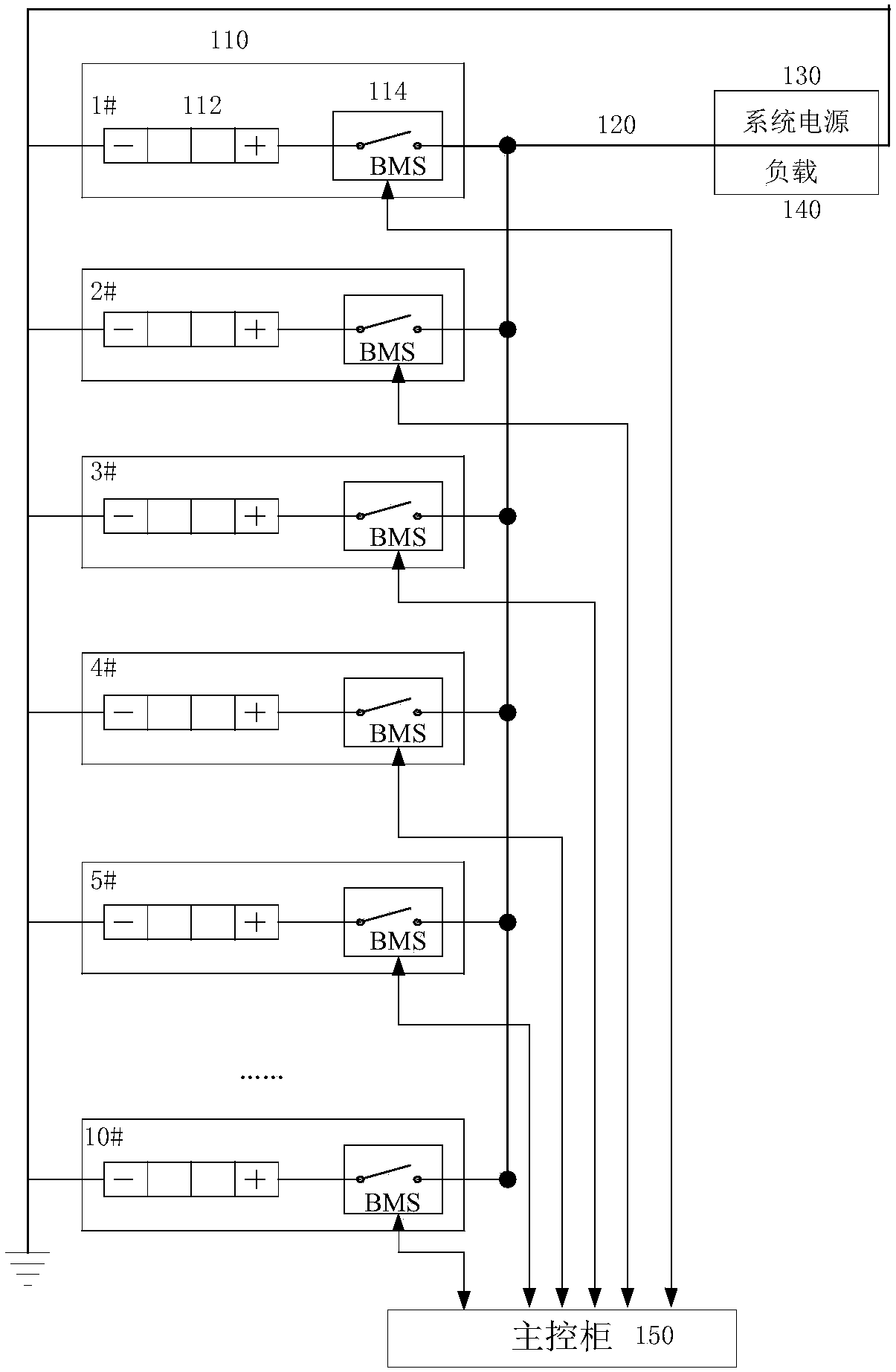
[0043] Combine Figure 2 to 4 The system structure shown is explained. When the system is initially powered on, the system power supply 130 works, and all the relays 116 of the battery cabinet 110 are disconnected, so that the battery cabinet 110 and the b...

specific Embodiment 2

[0047] Specific embodiment 2, please refer to Image 6 The power-on control method of the battery cabinet provided in this embodiment includes the following steps.

[0048] S12. Sort the average voltage value of each battery cabinet group not connected to the busbar from low to high into the first, second to nth battery cabinet group, where n is an integer greater than 2;

[0049] S22. Send a power-on command to the battery cabinet controllers of each battery cabinet in the first battery cabinet group, and each battery cabinet controller closes the corresponding relay after receiving the power-on command to complete the connection of the first battery cabinet group. Charging into the busbar;

[0050] S32. Send a conditional power-on command to the battery cabinet controller of each battery cabinet in the second battery cabinet group. After receiving the power-on command, the battery cabinet controller determines the second battery cabinet according to the conditional power-on command...

specific Embodiment 3

[0053] Specific Example 3, please refer to Figure 7 The power-on control method of the battery cabinet provided in this embodiment includes the following steps.

[0054] S13. Sort the average voltage value of each battery cabinet group that is not connected to the busbar from high to low;

[0055] S23. According to the sorting result, connect the battery cabinet group with the highest average voltage to the busbar for discharge;

[0056] S33. When the voltage value of the busbar drops to the average voltage value of the second highest battery cabinet group, connect the second highest battery cabinet group to the busbar for discharge;

[0057] S43, and so on, until all battery cabinets are connected to the busbar.

[0058] The discharging and voltage equalization and parallel connection mode of this embodiment is basically the same as the charging and voltage equalization and parallel mode of the specific embodiment 1. Combine Figure 2 to 4 The system structure shown is explained. Wh...


PUM


Abstract

The invention provides an energization control method of a battery cabinet for charging and discharging a lithium ion battery. The energization control method is characterized by comprising the following steps of (a) acquiring a voltage value of each battery cabinet needed to be energized; (b) grouping each battery cabinet in a mode that the battery cabinet with voltage difference smaller than a preset threshold by 20-40V is divided in a group; (c) controlling a voltage pressure value between each battery cabinet group and a busbar according to a voltage sharing mode, and sequentially connecting the battery cabinet group with minimum difference value between an average voltage and a busbar voltage in each battery cabinet group to the busbar; and (d) simultaneously charging and dischargingeach battery cabinet connected to the busbar.

Description

Technical field [0001] The present invention relates to the technical field of lithium ion batteries, in particular to a power-on control method and system of a battery cabinet for charging lithium ion batteries. Background technique [0002] Lithium batteries have high energy density, high single cell voltage, long life, no memory effect, and no pollution. Therefore, the use of lithium batteries for power supply is the development trend of battery applications. In high-power applications, firstly, lithium-ion battery cells are connected in series to form a lithium-ion battery pack to increase the power supply voltage, and then the lithium-ion battery packs are connected in parallel to increase the output power of the power supply. Both lithium-ion single cells and series-connected lithium-ion battery packs need to be monitored and managed by a battery cabinet controller including a relay. The lithium-ion battery pack and the battery cabinet controller together form the battery ...

Claims


Application Information

Patent Timeline
Patent Type & Authority Applications(China)
IPC IPC(8): H02J7/00H01M10/44
CPCH01M10/441H02J7/0013Y02E60/10
Inventor 陈财岳洪亮魏志立
Owner CONTEMPORARY AMPEREX TECH CO
Why Eureka
Try Eureka