Spine probe positioning and intersection puncture system

An intersection and probe technology, which is applied in the directions of stereotaxic surgical instruments, fixators, internal fixators, etc., can solve the problem of large human injury, and achieve the effect of avoiding injury.

Pending Publication Date: 2018-07-13
THE FIRST AFFILIATED HOSPITAL HENGYANG MEDICAL SCHOOL UNIV OF SOUTH CHINA
View PDF6 Cites 0 Cited by
  • Summary
  • Abstract
  • Description
  • Claims
  • Application Information

AI Technical Summary

Problems solved by technology

It solves the problem that the existing preoperative positioning method of spine-related surgery

Method used


Image

  • Spine probe positioning and intersection puncture system
  • Spine probe positioning and intersection puncture system
  • Spine probe positioning and intersection puncture system

Examples


Embodiment 1

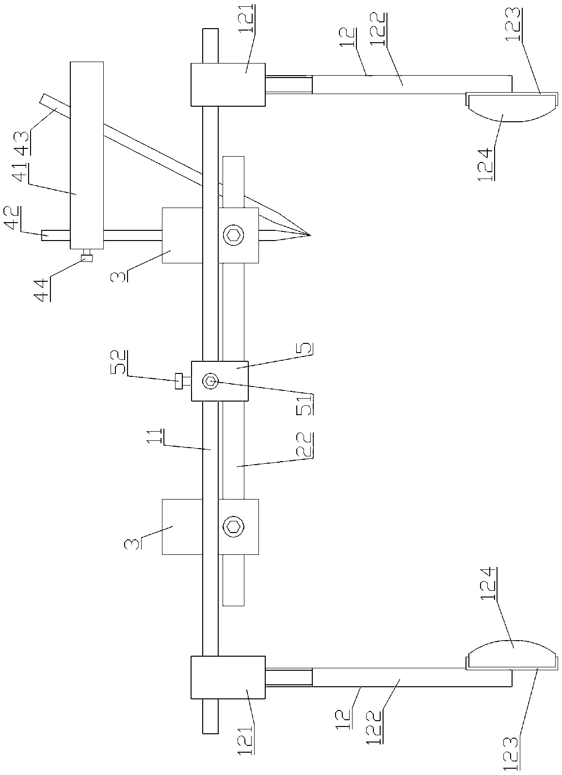
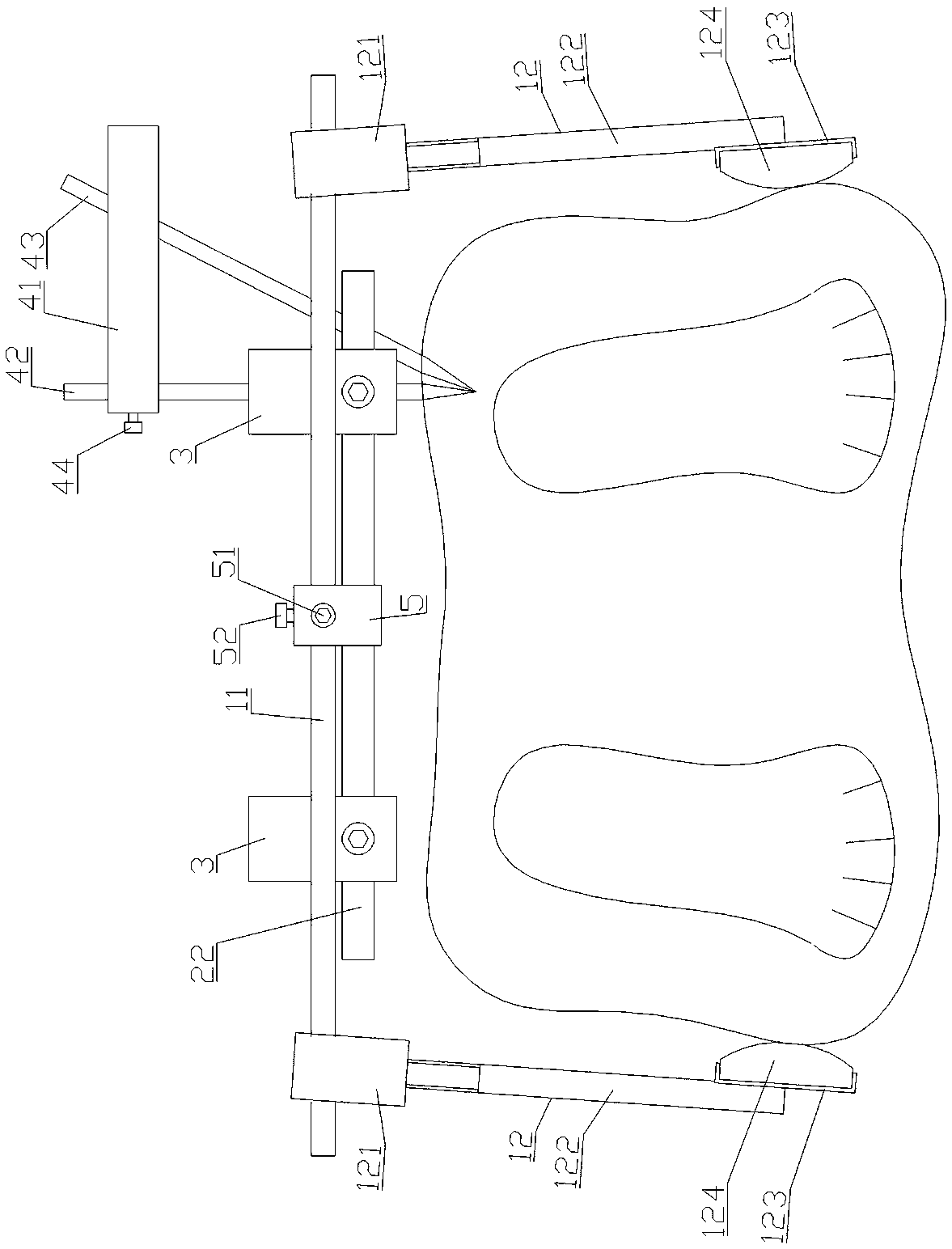
[0030] Such as Figure 1-6 As shown, the spinal probe positioning and nodal puncture system includes an iliac spine clamping frame, a spinous process midline positioning frame, a detection positioning block 3 and a triangular nodal puncture mechanism.

[0031] The iliac spine clamping frame includes a cross bar 11 and clamping components 12 arranged at two ends of the cross bar 11 . The clamping assembly 12 includes a connecting block A121 , a pressing rod 122 , a clamping seat 123 and an elastic pressing block 124 . The connecting block A121 is provided with a hole A1211 for the cross bar 11 to pass through, and it is movably installed on the cross bar 11 through the hole A1211. The hole A1211 of the connection block A121 forms a clearance fit with the cross bar 11 . One end of the pressure rod 122 is fixedly connected to the connecting block 121 , and the other end is welded and fixed to the clamping seat 123 . The elastic pressing block 124 is installed in the card seat ...

Embodiment 2

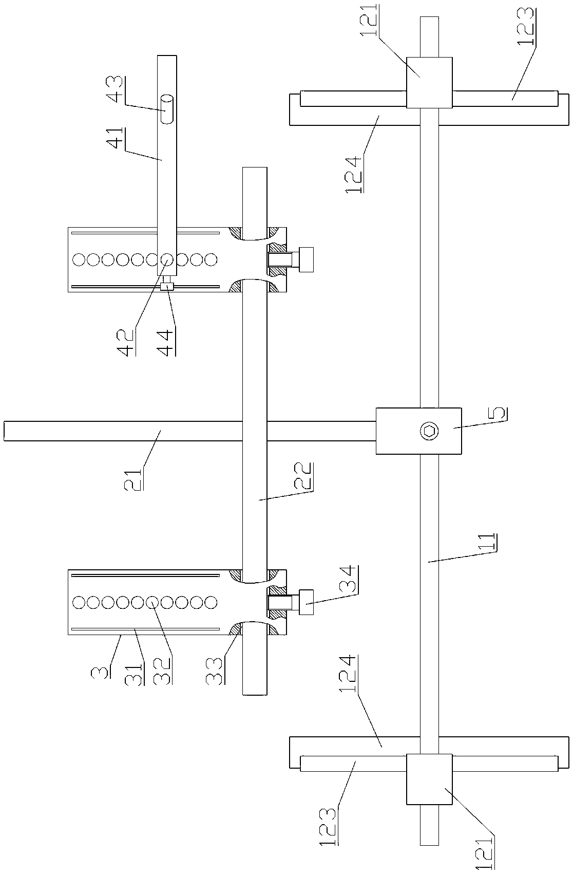
[0038] see Figure 7 Compared with Embodiment 1, this embodiment is only different in that: the spinous process midline positioning frame as a whole includes two spinous process positioning rods 21 and a horizontal connecting rod 22 . The horizontal connecting rod 22 is provided with a hole B221 through which the spinous process positioning rod 21 passes. The spinous process positioning rod 21 passes through the hole B221 and is movably connected with the horizontal connecting rod 22, and the two spinous process positioning rods 21 are arranged in parallel.

[0039] Two spinous process positioning rods 21 are better than one spinous process positioning rod 21 in positioning the centerline of the spinous process. One spinous process positioning rod 21 may slip to one side of the spinous process during positioning. When the protrusion positioning rod 21 is positioned, it can form a clamping effect to clamp the spinous process of the spine without lateral movement.

[0040] Brie...


PUM


Abstract

The invention discloses a spine probe positioning and intersection puncture system which comprises a spine iliac clamping frame, a spinous process center line positioning frame and a detection positioning block; the spina iliac clamping frame comprises a transverse rod and clamping assemblies arranged at the two ends of the transverse rod; the spinous process center line positioning frame is movably connected to the transverse rod and used for positioning the spine spinous process center line; the detection positioning block is movably connected to the spinous process center line positioning frame and used for positioning transverse processes on the two sides of the vertebra, the detection positioning block is provided with strip-shaped probe insertion regions and strip-shaped kirschner wire insertion regions, and the arrangement direction of the kirschner wire insertion regions is consistent with the arrangement direction of the probe insertion regions. By inserting a set of acupuncture needles (probes) into the probe positioning region of the detection positioning block at equal intervals, the bone anatomical structure of spine segments can be detected and positioned through different heights of the acupuncture needles, and therefore the portion needing puncture can be accurately judged; then, a triangular intersection puncture mechanism is adopted for performing percutaneouspuncture to achieve accurate nail entry, and human injuries caused by irradiation of an X-ray C-shaped arm machine are avoided.

Description

technical field [0001] The invention relates to an orthopedic surgical instrument, in particular to a spine probe positioning and intersection puncture system. Background technique [0002] At present, the preoperative positioning method for spine-related surgery is to perform percutaneous puncture positioning under the guidance of an X-ray C-arm machine. However, when the percutaneous puncture is positioned, X-rays are repeatedly irradiated, which is harmful to the human body. Contents of the invention [0003] The purpose of the present invention is to overcome the deficiencies of the prior art, and provide a spine probe positioning and intersection point puncture system. It solves the problem that the X-ray C-arm machine is used in the preoperative positioning method of the existing spine-related operations, and repeated X-ray exposures cause great harm to the human body. [0004] The technical solution of the present invention is: spinal probe positioning and interse...

Claims


Application Information

Patent Timeline
IPC IPC(8): A61B90/11A61B17/70
CPCA61B17/7076A61B90/11A61B2017/564
Inventor 宋西正王文军康禹
Owner THE FIRST AFFILIATED HOSPITAL HENGYANG MEDICAL SCHOOL UNIV OF SOUTH CHINA
Why Eureka
Try Eureka