Hydraulic support oil cylinder stainless steel connector base welding method

A technology of hydraulic support and welding method, which is applied in welding equipment, arc welding equipment, manufacturing tools, etc., can solve the problems of insufficient research on stainless steel weldability, and achieve the effect of solving many welding defects, improving welding seam forming, and large penetration.

Active Publication Date: 2018-07-13
ZHENGZHOU COAL MINING MACHINERY GRP +1
View PDF6 Cites 5 Cited by
  • Summary
  • Abstract
  • Description
  • Claims
  • Application Information

AI Technical Summary

Problems solved by technology

However, there is insufficient research on the weldability of this new type of stainless steel

Method used


Image

  • Hydraulic support oil cylinder stainless steel connector base welding method
  • Hydraulic support oil cylinder stainless steel connector base welding method
  • Hydraulic support oil cylinder stainless steel connector base welding method

Examples


Embodiment 1

[0019] The welding method of the stainless steel joint seat of the hydraulic support cylinder of the present invention includes the following specific steps:

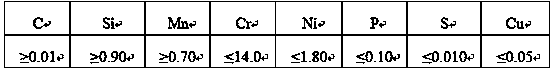
[0020] The first step is to use MAG welding, choose 80%Ar+20%CO 2 The mixed gas is used as the shielding gas, and low-alloy high-strength steel welding wire is selected. The chemical composition of the welding wire is (unit: mass fraction, %): C≤0.10%, Si: 0.40-0.82%, Mn: 1.00-1.30%, Ni: 0.20 -0.80%, Cu≤0.20%, S≤0.001%, P≤0.010%;

[0021] The second step is to preheat the stainless steel joint seat to be welded to 250°C, control the welding current to 200A, the welding voltage to 22V, and the welding speed to perform bottom welding;

[0022] The third step is to maintain the temperature between the weld passes at 250°C, control the welding current 230A, the welding voltage 24V, and the welding speed 500mm / min for filling welding.

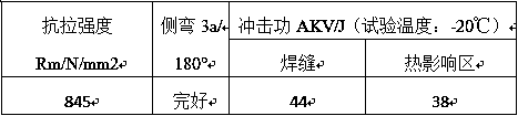
[0023] After testing, the physical and chemical indexes of the welded joint are:

[0024]

[0025]...

Embodiment 2

[0027] The welding method of the stainless steel joint seat of the hydraulic support cylinder of the present invention includes the following specific steps:

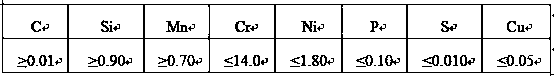
[0028] The first step is to use MAG welding, choose 80%Ar+20%CO 2 The mixed gas is used as a shielding gas, and a low-alloy high-strength steel welding wire is used. The chemical composition of the welding wire is (unit: mass fraction, %): C≤0.10%, Si: 0.40-0.82%, Mn: 1.00-1.30%, Ni: 0.20 -0.80%, Cu≤0.20%, S≤0.001%, P≤0.010%;

[0029] The second step is to preheat the stainless steel joint base to be welded to 300°C, control the welding current to 220A, the welding voltage to be 24V, and the welding speed to be 450mm / min for bottom welding;

[0030] The third step is to maintain the temperature between the weld passes at 400°C, control the welding current 250A, the welding voltage 26V, and the welding speed 700mm / min for filling welding.

[0031] After testing, the physical and chemical indexes of the welded joint are:

[0032] ...


PUM


Abstract

The invention discloses a hydraulic support oil cylinder stainless steel connector base welding method. MAG welding is adopted, 80% Ar+20% CO2 mixed gas serves as the protective gas, and a low-alloy high-strength steel welding stick is selected; a to-be-welded stainless steel connector base is preheated to 250-300 DEG C, the welding current is controlled to be 210+/-10 A, the welding voltage is controlled to be 23+/-1V, the welding speed is controlled to be 400-500 mm/min, and bottoming welding is conducted; the temperature between weld beads is kept to range from 250 DEG C to 400 DEG C, the welding current is controlled to be 240+/-10 A, the welding voltage is controlled to be 25+/-1V, the welding speed is controlled to be 500-700 mm/min, and filling welding is conducted. MAG welding is adopted, the welding manner is the same with the welding manner of other components of a hydraulic support, the welding process requirement is relatively simple, welding equipment and protective gas donot need to be replaced, and welding production organization is convenient. The low-alloy high-strength steel welding stick is adopted as a welding material for welding, the strength and tenacity ofa welding connector can be improved, and the welding material cost is reduced. Many frequently-happening welding problems that in the stainless steel connector base welding process, many welding defects exist, the welding line strength is low, and heat affected zone hardness is high are solved.

Description

Technical field [0001] The invention relates to a stainless steel welding method, in particular to a welding method of a stainless steel joint seat of a hydraulic support cylinder. Background technique [0002] At present, the column and jack joint seat materials produced by domestic hydraulic support manufacturers are all ordinary carbon steel or alloy steel, and their corrosion resistance is relatively poor. During the service process, the column jack leakage caused by the corrosion of the inner hole seal often occurs. The liquid phenomenon prevents the stent from working normally. In addition, during the overhaul of the support, a large number of joint seats often need to be replaced, which increases the frequency of cleaning of the hydraulic system and replacement of seals, resulting in a huge waste of costs and an extension of the maintenance cycle. In order to solve this problem, the joint seat must have high corrosion resistance: one method is to chemically treat the exis...

Claims


Application Information

Patent Timeline
Patent Type & Authority Applications(China)
IPC IPC(8): B23K9/167
CPCB23K9/167
Inventor 李福永韩振仙谷建军郭玉坤黄莹张自强孙远方凡乃峰兰志宇
Owner ZHENGZHOU COAL MINING MACHINERY GRP
Why Eureka
Try Eureka