Amorphous alloy composite shell and forming method and application thereof

An amorphous alloy and shell technology, which is applied to an amorphous alloy composite shell and its forming method and application fields, can solve the problems of not being recognized by consumers, difficult to use the shell, affecting the communication function, etc., and achieve good electromagnetic signal reception. and emission intensity, reducing the probability of deformation and damage, reducing the effect of product weight

Pending Publication Date: 2018-07-13
DONGGUAN JIANYE MATERIAL TECH CO LTD
View PDF11 Cites 2 Cited by
  • Summary
  • Abstract
  • Description
  • Claims
  • Application Information

AI Technical Summary

Problems solved by technology

[0003] While the trend of light weight and thinning is developing, for electronic products with communication functions, more effective sending and receiving signals can improve the applicability of products is also a problem that needs to be paid close attention to in the process of developing new housings, because Even if the product is extremely lightweight and thin, but it affects the use of communication functions, it is a waste of money and cannot be recognized by consumers.
In most metal materials, due to the low magnetic permeability, the interference to wireless signals is very serious (such as stainless steel materials), and communication products have high requirements for fixing and protecting internal components, so it is difficult to use plastic shells
Therefore, at this stage, in order to fix and protect the internal components without affecting the transmission and reception of wireless signals, multiple discontinuous metal shells with complex structures are often used, which not only sacrifices a lot of internal space, but also makes the parts manufacturing process complicated. The increase in the product assembly process greatly increases the production cost, and also makes the product volume remain high, making it difficult to be competitive
Or, use complex multi-channel CNC with T treatment plus nano-injection molding. In this way, the cost of the process will be greatly increased, which will put a lot of pressure on the overall product cost.
[0004] At present, in the prior art, no practical process has been proposed for the technical problem of how to reduce the weight of the metal shell while reducing the electromagnetic shielding, and also reduce the difficulty of the process.

Method used


Image

  • Amorphous alloy composite shell and forming method and application thereof
  • Amorphous alloy composite shell and forming method and application thereof
  • Amorphous alloy composite shell and forming method and application thereof

Examples


Embodiment 1

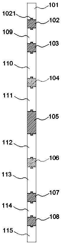
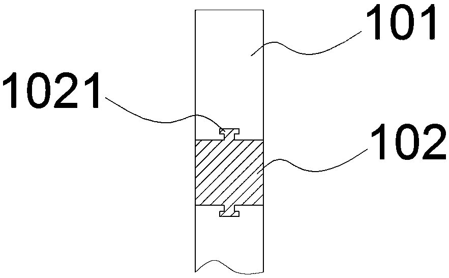
[0033] The amorphous alloy composite shell structure in Example 1 of the present invention is as attached figure 1 As shown, the schematic diagram is a cross-sectional schematic diagram of the side of the amorphous alloy composite shell. It can be seen from the accompanying drawings that it includes an amorphous alloy prefabricated component and a plastic bonding component. In this embodiment, the amorphous alloy prefabricated component includes an amorphous alloy prefabricated part 101, 109, 110, 111, 112, 113, 114, 115, the plastic bonding components include plastic bonding parts 102, 103, 104, 105, 106, 107, 108, the amorphous alloy prefabricated parts are all set as strips, and the plastic bonding parts It is a strip with the same thickness, and the amorphous alloy prefabricated parts and the plastic bonding parts are arranged at intervals, such as a plastic bonding part 102 between the amorphous prefabricated parts 101 and 109, and a plastic bonding part Plastic joint 104...

Embodiment 2

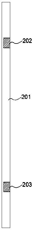
[0040] The amorphous alloy composite shell structure in Example 2 of the present invention is as attached image 3 As shown, the schematic diagram is a cross-sectional schematic diagram of the side of the amorphous alloy composite shell, which is attached image 3 It can be seen that it includes amorphous alloy prefabricated components and plastic bonded components. In this embodiment, the amorphous alloy prefabricated component includes an amorphous alloy prefabricated part 201, and the plastic bonded component includes plastic bonded parts 202 and 203. The amorphous alloy prefabricated parts are all set to In strip shape, the plastic bonding part is embedded in the amorphous alloy prefabricated part and has a thickness of 60-80% of the amorphous alloy prefabricated part. The above-mentioned structural features are suitable for a specific position in the internal structure that requires an additional anti-electromagnetic shielding function. At the same time, the outer surface...

Embodiment 3

[0046] The amorphous alloy composite shell structure in Example 3 of the present invention is as attached Figure 4 As shown, the schematic diagram is a cross-sectional schematic diagram of the side of the amorphous alloy composite shell, which is attached Figure 4 It can be seen that it includes amorphous alloy prefabricated components and plastic bonded components. In this embodiment, the amorphous alloy prefabricated component includes an amorphous alloy prefabricated part 301, and the plastic bonded component includes plastic bonded parts 302 and 303. The amorphous alloy prefabricated part 301 is a knuckle shape, and the plastic bonding part is a strip or plate-like structure that fits at the corners of the amorphous alloy prefabricated part. The above structural features are suitable for applications with particularly high requirements for light weight. In this embodiment, the thickness of the amorphous alloy prefabricated part can be as low as 0.05mm. After adding plast...


PUM

PropertyMeasurementUnit
thicknessaaaaaaaaaa
thicknessaaaaaaaaaa
thicknessaaaaaaaaaa

Abstract

The invention discloses an amorphous alloy composite shell which comprises an amorphous alloy prefabricated assembly and a plastic cement combination assembly. The amorphous alloy prefabricated assembly comprises one or more amorphous alloy prefabricated parts, the plastic cement combination assembly comprises multiple plastic cement combination parts, and the thickness of the amorphous alloy prefabricated parts is 0.05-0.5mm. The amorphous alloy prefabricated assembly and the plastic cement combination assembly are mutually cooperated for use to jointly form the needed composite shell. Preferentially, the thickness of the amorphous alloy prefabricated parts is 0.05-0.5mm and can meet the requirement for specific strength, the thickness is reduced by 50% or more compared with the thicknessof a common metal shell, and meanwhile the electromagnetic shield problem can be effectively solved by using the plastic cement combination assembly.

Description

technical field [0001] The invention belongs to the field of metal composite materials, and in particular relates to an amorphous alloy composite shell and its forming method and application. Background technique [0002] The design trend of electronic products in the prior art is more and more towards the direction of lightweight, concentrated functions and smaller volume. Conventional materials (such as commonly used stainless steel materials and plastic materials) are used as parts of the product for connection, fixing, and support. It must not only meet the index requirements such as strength and impact performance, but also be lighter and thinner as much as possible. The requirements for the shell are more stringent. It should not only fix, protect, and isolate the parts that need to be connected, but also not be too heavy and occupy too much space. At the same time, it must be wear-resistant and decorative. Therefore, it is very urgent for modern lightweight products ...

Claims


Application Information

Patent Timeline
Patent Type & Authority Applications(China)
IPC IPC(8): B29C45/14H05K5/02
CPCH05K5/0217B29C45/14
Inventor 黄利敏
Owner DONGGUAN JIANYE MATERIAL TECH CO LTD
Why Eureka
Try Eureka