Eureka AIR delivers breakthrough ideas for toughest innovation challenges, trusted by R&D personnel around the world.

A step-by-step splicing 3D printing system and printing method

A 3D printing and 3D printer technology, applied in the field of 3D printing, can solve the problems of high cost and poor use flexibility, achieve high printing accuracy and solve the effect of splicing errors

Active Publication Date: 2021-02-12
BMF NANO MATERIAL TECHNOLOGY CO LTD
View PDF9 Cites 0 Cited by
  • Summary
  • Abstract
  • Description
  • Claims
  • Application Information

AI Technical Summary

Problems solved by technology

[0004] In order to improve the printing format under the premise of satisfying the accuracy, the prior art CN201520983708.3 proposes to combine multiple DLP optical machines to achieve this, but the cost of this method is high, and the relative positions between each optical machine need to be precisely adjusted and adjusted. Fixed, not flexible enough to use

Method used


Image

  • A step-by-step splicing 3D printing system and printing method
  • A step-by-step splicing 3D printing system and printing method
  • A step-by-step splicing 3D printing system and printing method

Examples


Embodiment Construction

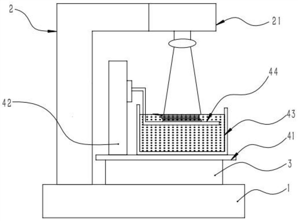
[0028] like figure 1 As shown, the present invention discloses a step-by-step splicing 3D printing system, including a control system and a 3D printer. The control system is connected to the 3D printer through communication. The 3D printer includes a fixed platform 1 and a The lens fixing column 2 and the printing mechanism at the upper end, the lens fixing column 2 is provided with a lithography lens 21 corresponding to the position of the printing mechanism, and an XY-axis motion platform is arranged between the printing mechanism and the fixed platform 1 3. The XY-axis motion platform 3 includes an X-axis motion mechanism and a Y-axis motion mechanism.

[0029] Both the X-axis movement mechanism and the Y-axis movement mechanism are screw movement mechanisms.

[0030] Described printing mechanism comprises connecting plate 41 and is located at the printing platform 44 on described connecting plate 41, printing platform elevating mechanism 42 and liquid tank 43, and describ...


PUM

PropertyMeasurementUnit
sizeaaaaaaaaaa

Abstract

The present invention provides a step-by-step splicing 3D printing system and printing method, including a control system and a 3D printer, the control system is connected to the 3D printer through communication, and the 3D printer includes a fixed platform and an upper end of the fixed platform. A lens fixing column and a printing mechanism, the lens fixing column is provided with a lithography lens corresponding to the position of the printing mechanism, an XY-axis movement platform is arranged between the printing mechanism and the fixed platform, and the XY-axis movement The platform includes an X-axis motion mechanism and a Y-axis motion mechanism. Setting up the XY-axis motion platform can ensure high printing accuracy while increasing the printing format through step-by-step splicing, and can effectively solve the splicing error in the splicing process.

Description

technical field [0001] The invention relates to the field of 3D printing, in particular to a step-by-step stitching 3D printing system and a printing method. Background technique [0002] At present, digital micromirror devices (Digital Micromirror Devices, DMD for short) are usually used in the 3D printing technology based on surface projection micro-stereolithography (DLP). DMD microlens arrays are used to provide exposed images. The size of each microlens in the DMD microlens matrix is ​​generally 7-10um, and the printing accuracy depends on the size of the microlens. In the surface projection micro-stereolithography (DLP) 3D printing technology, in order to further improve the precision to the sub-micron level, the DMD image is generally reduced by optical design, that is, the image reflected by the DMD is processed by the projection objective lens. Zoom out to achieve the purpose of improving printing accuracy. Because after the overall image is reduced, although the...

Claims


Application Information

Patent Timeline
Patent Type & Authority Patents(China)
IPC IPC(8): B29C64/129B29C64/245B29C64/393B33Y30/00B33Y50/02
CPCB33Y30/00B33Y50/02
Inventor 王焱华冯玉林何贺敬黄立赵卓贺晓宁方绚莱
Owner BMF NANO MATERIAL TECHNOLOGY CO LTD
Why Eureka
Eureka Blog
Learn More