Supercharge Your Innovation With Domain-Expert AI Agents!

Beam matching method and apparatus

A matching method and beam technology, applied in the field of communication

Active Publication Date: 2018-07-13
HUAWEI TECH CO LTD
View PDF4 Cites 2 Cited by
  • Summary
  • Abstract
  • Description
  • Claims
  • Application Information

AI Technical Summary

Problems solved by technology

The application of narrow beams can combat high-frequency path loss and improve coverage, but a key issue is how to realize the selection and alignment of the base station's transmitting beam and the user's receiving beam through beam scanning, that is, beam matching

Method used


Image

  • Beam matching method and apparatus
  • Beam matching method and apparatus
  • Beam matching method and apparatus

Examples


Embodiment Construction

[0086] Below in conjunction with accompanying drawing, embodiment of the present invention is described:

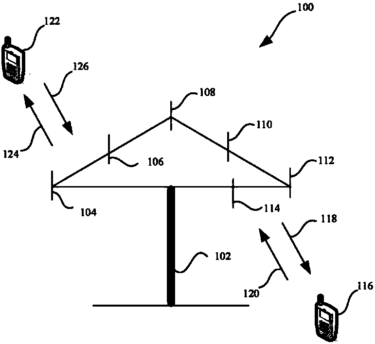
[0087] see figure 1 , figure 1 It is a schematic diagram of a communication system architecture involved in an embodiment of the present invention. The system includes a receiver device and a transmitter device. The receiving end device in the embodiment of the present invention can communicate with one or more core networks via a radio access network (Radio AccessNetwork, RAN), and the receiving end device can refer to an access terminal, a subscriber unit, a subscriber station, a mobile station, a mobile station , a remote station, a remote terminal, a mobile device, a user terminal, a terminal, a wireless communication device, a user agent, or a user device. The access terminal may be a cellular phone, a cordless phone, a Session Initiation Protocol (SIP) phone, a Wireless Local Loop (WLL) station, a Personal Digital Assistant (PDA) , referred to as "PDA"), handheld ...


PUM


Abstract

Embodiments of the invention provide a beam matching method and apparatus. The beam matching method comprises the following steps: determining a beam scanning parameter group; transmitting the beam scanning parameter group to a receiving end device; and scanning a transmitting beam based on the beam scanning parameter group. Another beam matching method comprises the following steps: receiving a beam scanning parameter group from a transmitting end device; and executing beam matching based on the beam scanning parameter group. Corresponding apparatuses are also disclosed. Uniform management ofmultiple beam matching processes can be achieved through a unified beam scanning parameter group, thereby simplifying the beam matching process.

Description

technical field [0001] The present invention relates to the field of communication technologies, in particular to a beam matching method and device. Background technique [0002] Currently, the next-generation evolved system has higher requirements in terms of network performance and user experience, and the fifth-generation mobile communication system (5 th -Generation, 5G) brings greater challenges. Due to its rich spectrum resources, the millimeter wave frequency band has become one of the main working frequency bands of 5G technology. When the millimeter wave frequency band is used, due to the large path loss in the data transmission process of the frequency band, the anti-fading performance is poor, and the coverage is improved by sending narrow beams. The application of narrow beams can counteract the high-frequency path loss and improve coverage, but a key issue is how to realize the selection and alignment of the base station's transmitting beam and the user's rece...

Claims


Application Information

Patent Timeline
IPC IPC(8): H04B7/08H04B7/06H04W72/04
CPCH04B7/0617H04B7/0695H04B7/088H04W72/046H04W72/23H04L5/0048H04L5/0023H04L5/0091H04W72/0446H04W72/542
Inventor 武露
Owner HUAWEI TECH CO LTD
Features
  • R&D
  • Intellectual Property
  • Life Sciences
  • Materials
  • Tech Scout
  • Unparalleled Data Quality
  • Higher Quality Content
  • 60% Fewer Hallucinations
Learn More