CT machine, scanning method and image reconstruction method
A technology of tomography and computer, applied in image data processing, graphic image conversion, computerized tomography scanner, etc., can solve problems such as aliasing artifacts, achieve high-quality three-dimensional imaging, good isotropic resolution effect, eliminate The effect of Z-direction aliasing artifacts
- Summary
- Abstract
- Description
- Claims
- Application Information
AI Technical Summary
Problems solved by technology
Method used
Image
Examples
Embodiment 1
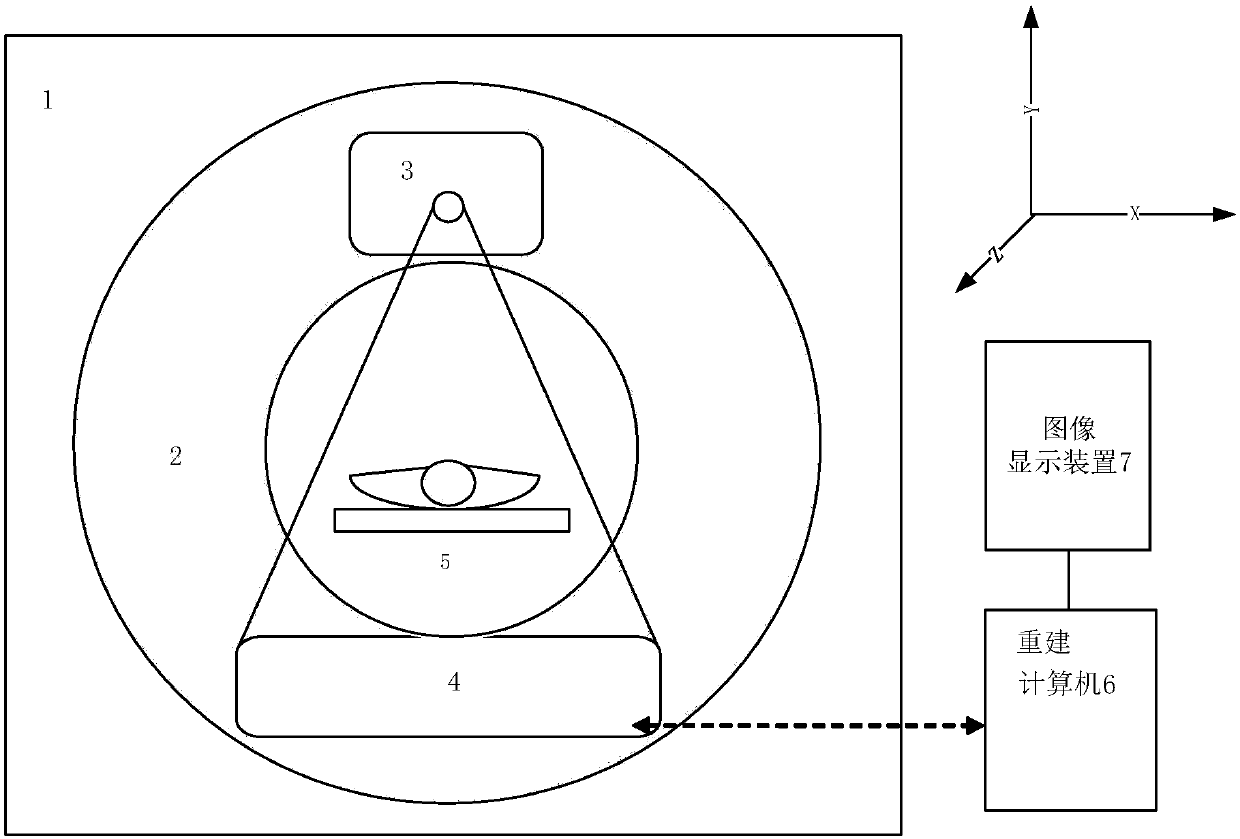
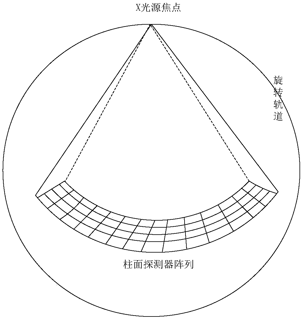
[0077] Such as Figure 1-2 As shown, a computer tomography apparatus provided by an embodiment of the present invention includes a fixed frame 1, a rotating frame 2, a light source generating device 3, a signal detection device 4, and a scanning target supporting device 5: the rotating frame 2 can surround XY A certain fixed point on the plane rotates; the scanned target supporting device 5 is fixed along the Z direction to meet the tomographic trajectory, and the XYZ coordinate system meets the definition of the right-handed system; the light source generating device 3 is installed on the rotating frame 2, It can output the scanning light of the cone beam, and quickly switch the focus position along the Z direction during adjacent sampling periods, while the center position of the light source continuously moves along the Z direction; the signal detection device 4 is installed on the rotating frame 2, and The position of the light source generating device 3 is relatively, and ...
Embodiment 2
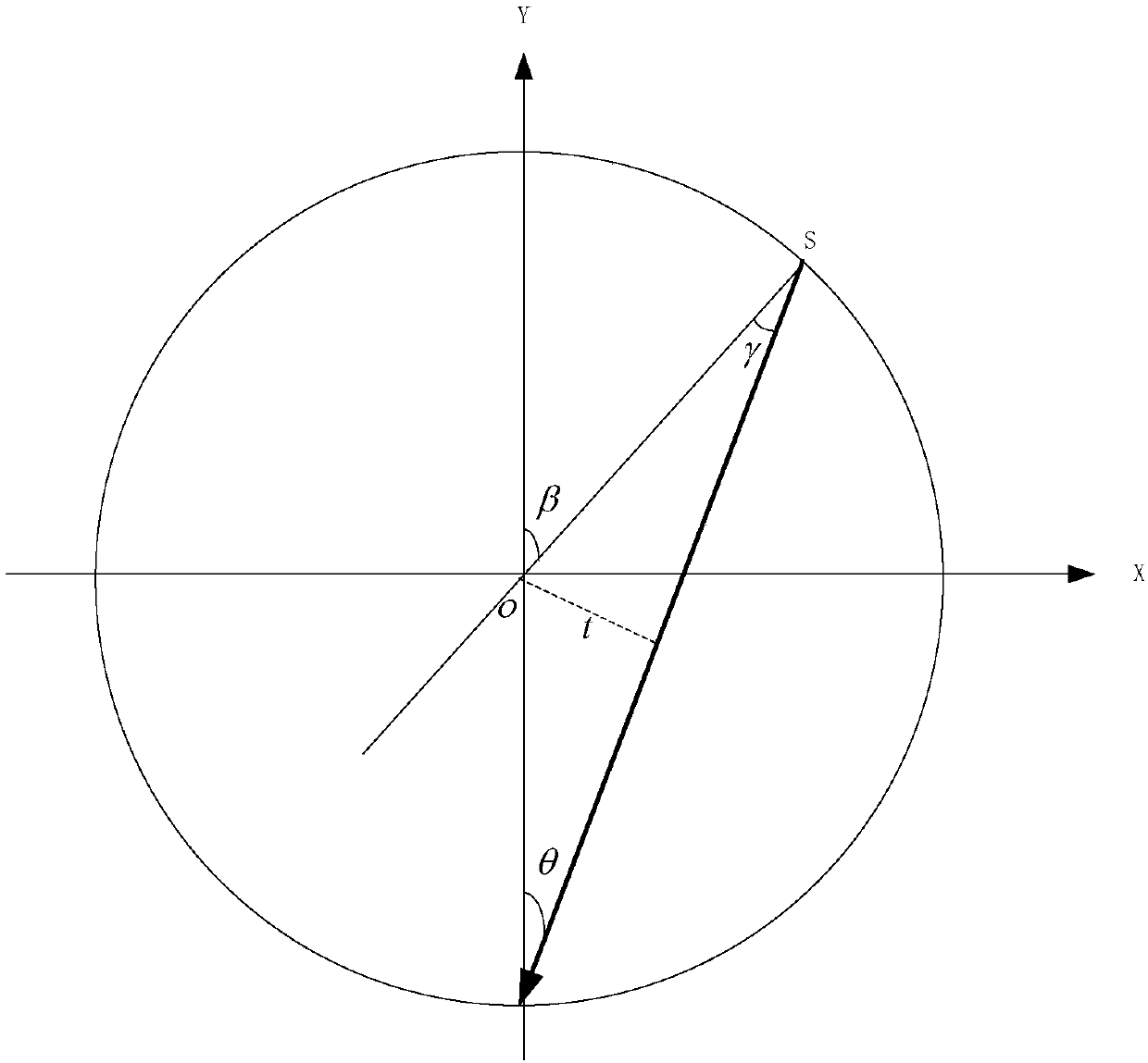
[0084] Such as image 3 As shown, the embodiment of the present invention also provides a scanning control method using any of the above-mentioned computed tomography apparatus, wherein the above-mentioned computed tomography apparatus will not be described in detail. The scanning control method may include the following steps:
[0085] S101: While the light source generating device 3 and the signal detecting device 4 are rotating and scanning in the XY plane, the scanned target supporting device 5 is fixed in the Z direction to meet the tomographic trajectory. Trigger sampling in equal-angle mode, the total number of projected samples is an even number, defined as N, and the range of acquisition can be less than one circle, exactly one circle, or more than one circle;
[0086] S102: When the tomographic scan is started, the position of the light source generating device's focus on the anode target surface is continuously and rapidly switched, and the center position of the light s...
Embodiment 3
[0104] Such as image 3 As shown, the embodiment of the present invention also provides a method for image reconstruction based on the data obtained by any of the above-mentioned scan control methods. The CT machine adopts the CT machine described in Embodiment 1, and the scanning method is as in the embodiment. 2 said, not repeat them here. The method of image reconstruction for the data obtained by the scanning control method includes the following steps:
[0105] S201: Perform necessary preprocessing on the scanned data;
[0106] S202: rearrange the data pre-processed in step S201;
[0107] S203: filtering and weighting the data rearranged in step S202;
[0108] S204: Back-project the filtered and weighted data in step S203;
[0109] S205: Perform post-processing on the back-projected data in step S204 to obtain an image that can be used for diagnosis.
[0110] In particular, the step S202 includes:
[0111] S2021: At different projection angles, the radius of rotation and channel an...
PUM
 Abstract
Description
Claims
Application Information
 - R&D
- Intellectual Property
- Life Sciences
- Materials
- Tech Scout
- Unparalleled Data Quality
- Higher Quality Content
- 60% Fewer Hallucinations
Browse by: Latest US Patents, China's latest patents, Technical Efficacy Thesaurus, Application Domain, Technology Topic, Popular Technical Reports.
© 2025 PatSnap. All rights reserved.Legal|Privacy policy|Modern Slavery Act Transparency Statement|Sitemap|About US| Contact US: help@patsnap.com


