Lug laser cutting device, workbench assembly and lug laser cutting method

A laser cutting and workbench technology, applied in laser welding equipment, manufacturing tools, metal processing equipment, etc., can solve problems such as battery short circuit, dust removal effect not reaching the optimal state, explosion, etc.

Pending Publication Date: 2018-07-17
SHENZHEN GEESUN INTELLIGENT TECHNOLOGY CO LTD
View PDF4 Cites 0 Cited by
  • Summary
  • Abstract
  • Description
  • Claims
  • Application Information

AI Technical Summary

Problems solved by technology

However, due to the softness of the pole piece material, traditional dust removal and laser cutting will produce corresponding contradictions and interference
The traditional vacuum device is basically located above or below the pole piece. In order to prevent the vacuum device from deforming the pole piece, there will be a large gap between the dust collection device and the pole piece, and the suction force should not be too large; The bottom plate dust removal can not be opened too much, the suction is too large, the pole piece will be adsorbed on the cutting bottom plate, and the pole piece cannot continue to be transported, and the suction force will not make the dust removal effect reach the ideal state.
After laser cutting, the spatter, dust and current collector slag generated by cutting will fall on the pole piece, and because laser cutting is a very high temperature cutting, these spatter, dust and current collector slag will be melted on the pole piece. On the pole piece, it is very difficult to remove. In the subsequent winding or lamination process, it is very likely to pierce the separator and cause the battery to short circuit or explode, which greatly reduces the yield and safety of the product.

Method used


Image

  • Lug laser cutting device, workbench assembly and lug laser cutting method
  • Lug laser cutting device, workbench assembly and lug laser cutting method
  • Lug laser cutting device, workbench assembly and lug laser cutting method

Examples


Embodiment Construction

[0027] Hereinafter, the present invention will be further described in detail through specific embodiments in conjunction with the drawings.

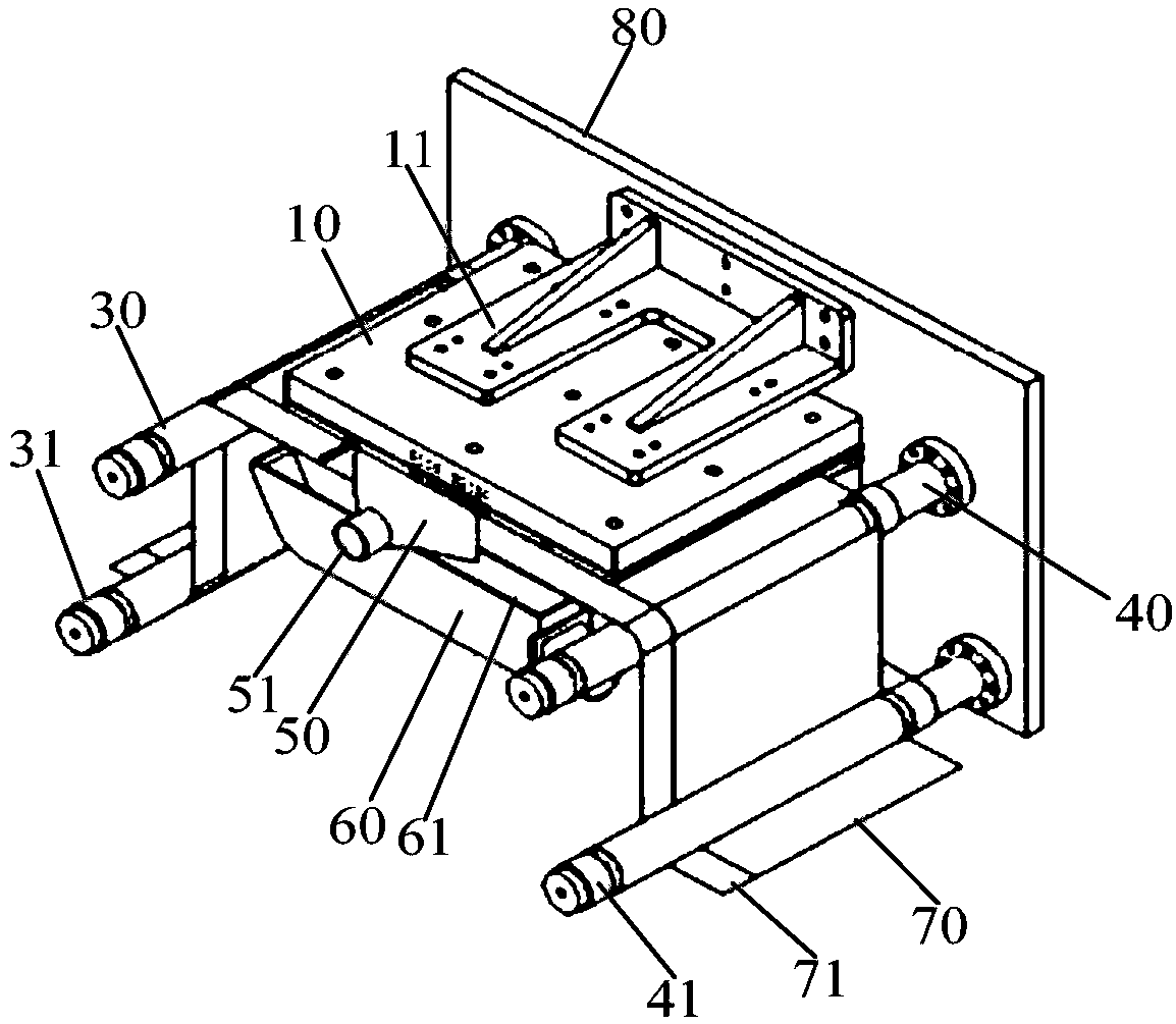
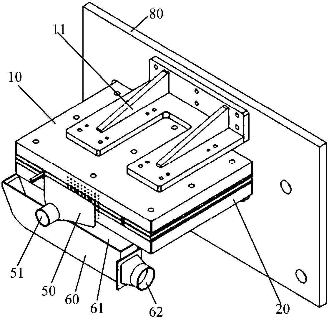
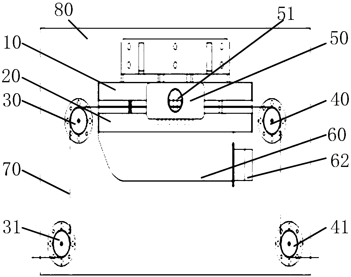
[0028] See Figure 1-Figure 4 As shown, the workbench assembly of the laser electrode cutting device provided in this embodiment includes: an upper air duct plate 10, an upper support plate 11, a lower air duct plate 20, a lower support plate 21, a first feed roller 30, and a first sheet The tension roller 31, the second feed roller 40, the second tension roller 41 and the mounting plate 80.

[0029] Specifically, the upper air duct plate 10 is installed on the upper supporting plate 11, the lower air duct plate 20 is installed on the lower supporting plate 21, the upper supporting plate 11 and the lower supporting plate 21 are installed on the mounting plate 80 up and down, and the two supporting plates There is a certain distance between the upper air duct plate 10 and the lower air duct plate 20, so that the pole piece 70 can pass betwee...


PUM


Abstract

The invention discloses a lug laser cutting device, a workbench assembly and a lug laser cutting method. The workbench assembly comprises an upper air channel plate and a lower air channel plate. Theupper air channel plate is arranged above the lower air channel plate. An interval space allowing the lug to pass is reserved between the upper air channel plate and the lower air channel plate. The bottom face of the upper air channel plate and the top face of the lower air channel plate are each provided with multiple air holes. The upper air channel plate and the lower air channel plate blow air into the interval space through the multiple air holes so as to remove dust. When the workbench assembly cuts the lug, the upper air channel plate and the lower air channel plate blow air to the interval space so as to remove dust, the stability of a conveyed pole plate in the interval space can be improved at the same time, shake of the pole plate in the cutting process is restrained, and therefore an out-of-focus laser and other phenomena can be avoided.

Description

Technical field [0001] The invention relates to the field of lithium ion battery production equipment, and in particular to a laser electrode cutting device, a worktable assembly and a laser cutting method for the electrode ear. Background technique [0002] In the laser cutting process of lithium ion battery tabs, the traditional laser cutting process is to transport the pole pieces through the transmission of rollers. In the laser cutting area, there is a cutting base plate to support the pole pieces and correspond to the cutting track. The groove ensures that the pole piece at the cutting position is in a suspended state; the spatter, dust, and current collector slag generated during the cutting process are discharged downward through the groove, and then sucked away by the dust collector. However, due to the soft nature of the pole piece material, traditional dust removal and laser cutting will produce corresponding contradictory interference. The traditional vacuum device i...

Claims


Application Information

Patent Timeline
Patent Type & Authority Applications(China)
IPC IPC(8): B23K26/38B23K26/70
CPCB23K26/38B23K26/702
Inventor 吴学科程志保陈荣军阳如坤
Owner SHENZHEN GEESUN INTELLIGENT TECHNOLOGY CO LTD
Why Eureka
Try Eureka