Cotton filling machine
A cotton filling machine and cotton machine technology, applied in the textile field, can solve the problems of low work efficiency, affecting the fullness and elasticity of the product, and insufficient expansion of the cotton body.
- Summary
- Abstract
- Description
- Claims
- Application Information
AI Technical Summary
Problems solved by technology
Method used
Image
Examples
Embodiment 1
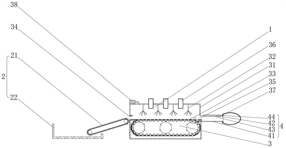
[0041] see figure 1 , the present invention provides a technical solution: a cotton filling machine, including a cotton filling machine body 1 composed of a conveying mechanism 2, a cotton loosening mechanism 3 and a cotton filling mechanism 4, the conveying mechanism 2 includes a conveyor belt 21, and the right side of the conveyor belt 21 The side is connected with loosening mechanism 3, and the left side of conveyor belt 21 is provided with material frame 22, and loosening mechanism 3 comprises shell 31, and the inside of shell 31 is respectively provided with elastic cotton mechanism 32 and pulling mechanism 33, and the left side of shell 31 A feed port 34 is provided, and a discharge port 35 is provided on the right side of the casing 31. The top of the casing 31 is fixedly connected to the right blower 36, and the right end of the discharge port 35 communicates with the cotton filling mechanism 4, and the right side of the cotton filling mechanism 4 A filling product 37 ...
Embodiment 2
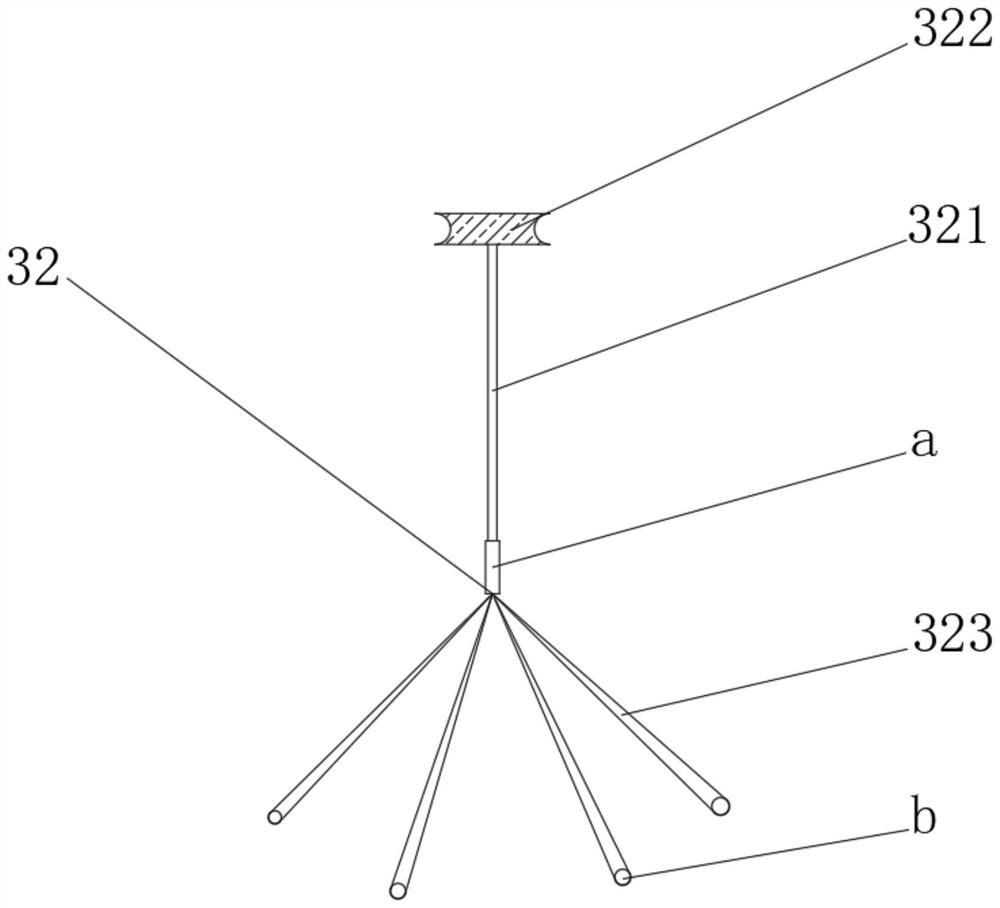
[0044] see Figure 1-5 , On the basis of Embodiment 1, the present invention provides a technical solution: the elastic cotton mechanism 32 includes a push rod 321, the top of the push rod 321 is fixedly connected with a rotating disk 322, and the rotating disk 322 is located inside the casing 31 and is connected to the casing 31 The inner rotation connection of the rotating disk 322 is connected with the servo motor 38 through the belt, the bottom of the ejector rod 321 is fixedly connected with the vibration mechanism a, the bottom of the vibration mechanism a is fixedly connected with the vibration rod 323, and the bottom of the vibration rod 323 is fixedly connected with There is a pullback ball b.
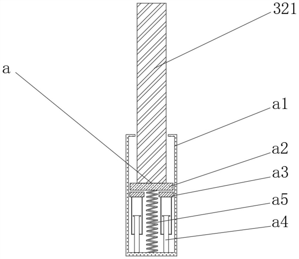
[0045] The oscillating mechanism a includes an oscillating frame a1, an electromagnet a2 is arranged inside the oscillating frame a1, the top of the electromagnet a2 is fixedly connected to the bottom of the ejector rod 323, the outer wall of the electromagnet a2 is slidingly ...
Embodiment 3
[0050] see Figure 1-7 On the basis of Embodiment 1 and Embodiment 2, the present invention provides a technical solution: the pulling mechanism 33 includes a pulling block 331, and both sides of the pulling block 331 are fixedly connected to springs 332, and the end of the spring 332 away from the pulling block 331 is connected to the The inside of the shell 31 is fixedly connected, the top of the pull block 331 is fixedly connected to the friction block 333 , both sides of the pull block 331 are rotatably connected to elastic plates 334 , and the bottom of the pull block 331 is provided with a snap-fit mechanism c.
[0051] The engaging mechanism c includes an engaging ring c1, the bottom of the engaging ring c1 is rotatably connected to an indexing rod c2, the outside of the indexing rod c2 is rotatably connected to an indexing block c3, and the inside of the engaging ring c1 is provided with an engaging ball c4 , The bottom of the locking ball c4 is fixedly connected wit...
PUM
 Abstract
Description
Claims
Application Information
 - R&D
- Intellectual Property
- Life Sciences
- Materials
- Tech Scout
- Unparalleled Data Quality
- Higher Quality Content
- 60% Fewer Hallucinations
Browse by: Latest US Patents, China's latest patents, Technical Efficacy Thesaurus, Application Domain, Technology Topic, Popular Technical Reports.
© 2025 PatSnap. All rights reserved.Legal|Privacy policy|Modern Slavery Act Transparency Statement|Sitemap|About US| Contact US: help@patsnap.com


